

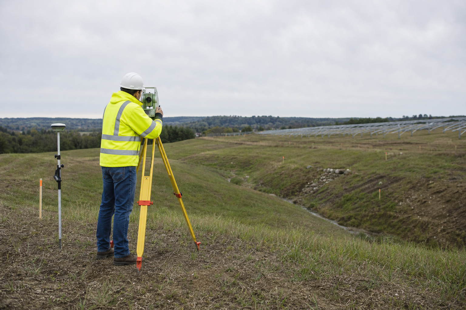
Authorship, review and evidence boundary
- Technical review
- East Baoyu Engineering Editorial Team
- Reviewed
- 2026-07-29
- Scope
- General engineering and procurement guidance. This article is not a project-specific design, capacity statement, certificate, warranty, code interpretation or contract requirement.
Evidence basis: Official and public references identified in the article, together with original editorial diagrams. Project values and release decisions require qualified review under the applicable project responsibilities.
Read the Editorial PolicyA contour drawing can look complete and still be unusable for structural layout. Its coordinate reference may be unclear, points may omit the breaks that control grading and drainage, visible obstacles may not be coded, or the native surface model may be missing. The design team then appears to have terrain information while every downstream calculation rests on unverified assumptions.
Good solar farm topographic survey requirements begin with the decisions the data must support. The specification should connect survey control and field observations to array layout, post or pile scheduling, access and grading coordination, drainage interfaces and construction set-out. It should also define what the survey does not prove. Topography is one controlled input; it is not a substitute for legal boundary, underground utility, hydrological, environmental or geotechnical work.
1. Work backward from structural and civil decisions
Start the brief by listing the users of the terrain model and the decisions each user will make. Structural teams need dependable coordinates and levels at support locations, plus slopes and discontinuities that affect exposed height, embedment, head adjustment and member geometry. Layout teams need boundaries, exclusions, row-access rules and a surface that can be queried between labelled contours. Civil teams need flow paths, channels, banks, culverts and access transitions. Construction teams need recoverable control and an approved set-out basis.
Write a use matrix before naming a technology or point density. A preliminary layout model may tolerate broader uncertainty than final foundation scheduling. A drone surface suitable for planning may still require terrestrial observations at shaded features, steep banks or critical interfaces. The specification should state the design stage, intended decisions, excluded uses and the authority that accepts the survey for each release.
Use the East Baoyu Solar Mounting Design Input Checklist to align topography with the broader project input register. This guide goes deeper into the survey-to-structure handoff and does not repeat the whole design checklist.
2. Use the six-layer Survey-to-Structure Chain
The chain below is an East Baoyu editorial control framework, not a surveying standard. Its value is completeness: every layer has an observation or rule, a controlled output and a downstream consumer. If one link is missing, the final drawing can be visually polished but operationally weak.
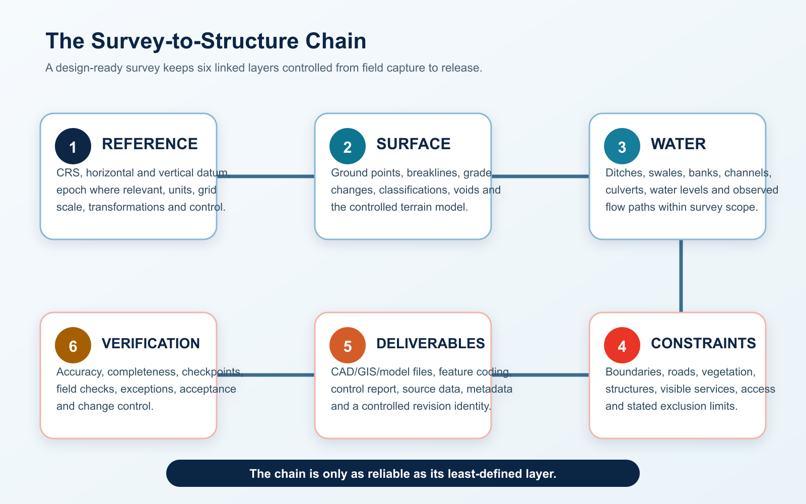
| Layer | Required question | Controlled output |
|---|---|---|
| Reference | Where are coordinates and levels defined? | CRS, datum, epoch if relevant, units, grid rule and control schedule. |
| Surface | Which geometry must the model preserve? | Coded points, breaklines, terrain model, contours and voids. |
| Water | Which features influence flow or erosion interfaces? | Channels, swales, banks, culverts, crossings and observed water levels. |
| Constraints | What visible feature limits layout or access? | Fences, roads, structures, vegetation limits and defined exclusions. |
| Deliverables | Can the design team query and trace the source? | Native model, exchange files, feature codes, metadata, report and revision. |
| Verification | How was quality tested for the intended use? | Control checks, residuals, sample comparisons, exceptions and acceptance record. |
3. Lock coordinate reference, datum, units and control
Name the horizontal coordinate reference system, vertical datum, units and any project-grid transformation. Where time-dependent coordinates matter, include the coordinate epoch and transformation route. Do not accept labels such as local grid or assumed datum without a recoverable definition. A project grid can be practical, but its origin, orientation, scale treatment and relationship to the governing reference must be documented.
ISO 19111:2019 provides the conceptual framework for coordinate reference systems and coordinate operations. It does not choose the correct CRS for a project. The surveyor and project authority must make that selection for the jurisdiction, site extent and required use.
Provide a control schedule with identifiers, descriptions, coordinates, levels, monument type, establishment method, condition and recovery information. Distinguish primary control from temporary construction marks. State how control will be checked before and after the survey and how later set-out teams will confirm they are using the same controlled basis. A coordinate list without site descriptions or check evidence is fragile handover data.
4. Capture a surface that preserves design geometry
The field method should capture terrain changes that affect design, not merely meet a uniform spacing rule. Observe ridges, toes and crests of slopes, banks, ditches, road edges, berms, retaining features, pads, depressions, abrupt grade changes and other breaklines. Increase observation where the surface changes rapidly or where a support, access route or drainage interface is sensitive. Record areas that cannot be observed and do not interpolate across them without an explicit method and flag.
| Feature group | Capture expectation | Design relevance |
|---|---|---|
| General ground | Coded observations sufficient to model the intended surface and its uncertainty. | Row grading, support levels and layout screening. |
| Breaklines | Observed and connected crest, toe, bank, ditch, road and berm geometry. | Prevents smoothing across structural or hydraulic discontinuities. |
| Hard surfaces | Edges, crowns, kerbs, inverts and transitions where relevant. | Access, delivery, drainage and level coordination. |
| Structures | Visible footprints, corners, heights or threshold levels as specified. | Clearance, demolition or retention interfaces. |
| Vegetation / obscuration | Limits and confidence/void flags; ground method identified. | Shows where surface reliability may differ. |
Contours are a derived presentation of the terrain model, not source observations. Specify the native surface format and breaklines as deliverables, then choose contour intervals appropriate to scale and use. Do not infer the model's accuracy from a dense contour display. The survey report should explain interpolation, filtering, ground classification, smoothing and any manual editing that materially affected the surface.
5. Map water, access and visible physical constraints
Show visible channels, swales, banks, culverts, headwalls, inlets, outlets, ponded areas and erosion features requested by the project. Include invert, crown or top levels where those values support civil coordination. Record the observation date and distinguish observed water level from a design flood or modelled level. A dry ditch on survey day may still be a meaningful flow path.
The NREL PV-SMaRT research tool shows why slope, soils, ground cover and array configuration interact in stormwater analysis. The survey supplies terrain and visible-feature inputs; it does not calculate drainage capacity, define flood levels or replace a qualified civil design.
Also capture the visible constraints named in the brief: boundaries or supplied boundary lines, fences, gates, roads, tracks, buildings, overhead services, poles, inspection chambers, rock outcrops, vegetation limits and access restrictions. Identify whether a line was surveyed, supplied by another party or interpreted from imagery. A visible chamber cover does not prove the route or depth of an underground utility.
6. Specify accuracy by use and feature
Avoid a single sentence asking for an accurate survey. State the positional quality needed for each use and feature, the confidence or reporting convention, how it will be tested and what evidence must be delivered. Horizontal and vertical requirements can differ. Hard-edged features, ground points under vegetation and a generalized planning surface may require different methods and quality statements.
ISO 19157-1:2023 defines principles for describing, evaluating and reporting geographic-data quality. It deliberately does not prescribe one universal acceptable quality level. Current ASPRS Positional Accuracy Standards provide method-specific accuracy context for modern mapping. The project still needs an intended-use requirement and an agreed acceptance process.
Requirement – state the quality target, confidence/reporting convention, feature class and intended use.
Method – identify independent checks, test locations, field or processing controls and excluded areas.
Evidence – provide residuals, check results, calibration/control records, exceptions and responsible sign-off.
Disposition – define acceptance, correction, resurvey and controlled-use routes before design release.
7. Choose technology by deliverable and limitations
Total stations, GNSS, terrestrial laser scanning, airborne lidar and photogrammetry can all contribute, but no technology is inherently fit for every project use. Selection should consider vegetation, satellite visibility, line of sight, surface texture, site scale, steepness, required feature coding, safety, weather, programme and how independent checks will be obtained. Hybrid surveys are common because one method can cover open ground efficiently while another resolves critical edges or obscured areas.
The USGS Lidar Base Specification 2025 Revision A is a useful public example of explicit classification, breakline, void, accuracy and metadata controls. It is a US 3DEP specification, not a universal solar-farm requirement. Borrow the discipline of stating requirements, not its project-specific values without review.
8. Use one controlled terrain model for four consumers
A controlled terrain model can serve layout, structural, civil and construction teams, but each team consumes different features and has different release risks. The common model needs one revision identifier, a stated reference system and a record of processing. Derived products should cite that source revision so a later surface update does not silently leave row schedules or setting-out files behind.
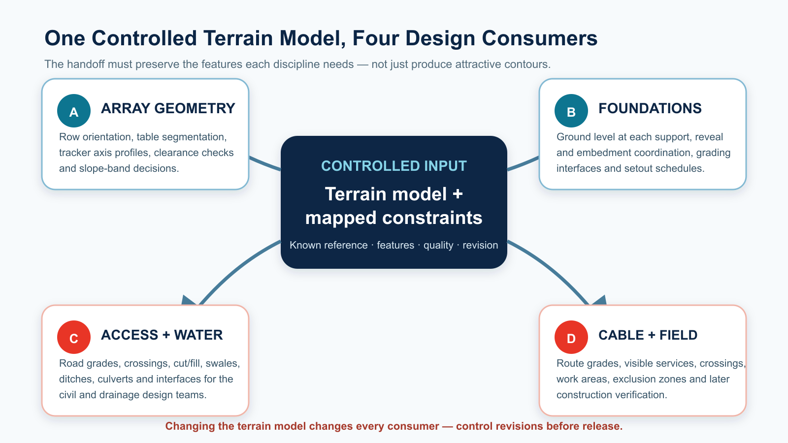
For fixed-tilt systems, the model supports row grading, support elevations, exposed length checks and table-to-table transitions. Trackers add sensitivity to torque-tube geometry, drive position and row alignment. Flexible systems require controlled anchor coordinates, elevations, span geometry and clearance interfaces. These are design uses, not evidence that topography alone determines structural suitability.

Compare system-level inputs in Fixed versus tracking PV, Solar tracker wind load and stow strategy and Flexible PV span, pretension and dynamics. Each system still needs project-specific structural and geotechnical design.
9. Deliver source data, metadata and revision control
A PDF plan is useful for review but usually insufficient for design. Require the agreed native and exchange formats, coded survey points, breaklines, terrain model, contours, control schedule, feature catalogue, coordinate-system definition, survey report, accuracy/quality report and an issue register. State software versions or schema requirements where interoperability matters. Keep raw observations or traceable source files according to the project's retention rules.
| Package | Minimum controlled content |
|---|---|
| Reference | CRS, vertical datum, units, epoch if relevant, grid transformation and control schedule. |
| Source observations | Coded points, breaklines, method/source tags and obscured or excluded areas. |
| Design model | Triangulated or agreed terrain surface, voids, contours and feature layers. |
| Reports | Method, equipment, dates, processing, quality checks, limitations and responsible approval. |
| Issue control | File manifest, formats, revision, status, coordinate checksums or equivalent and transmittal. |
Define the status of each issue: preliminary, for coordination, for design or for construction. If a survey is updated, provide a change summary and identify affected areas. Design teams should not overwrite the prior surface without checking which layouts, foundation schedules, quantities and set-out products depend on it.
10. Keep separate survey scopes separate
A topographic survey records surface geometry and specified visible features. It should not be presented as proof of title, underground services, soil conditions, flood risk, drainage capacity, habitat constraints or final grading feasibility. Those scopes may use the same coordinates, but they require their own competent methods, evidence and approvals.
| Separate scope | Topographic interface | Do not infer |
|---|---|---|
| Legal boundary | Show supplied or separately surveyed line with source/status. | Ownership, title or legal definition from a visual fence. |
| Underground utilities | Show visible covers, markers and supplied records distinctly. | Route, depth, status or completeness without utility investigation. |
| Geotechnical | Provide terrain and investigation-location coordinates. | Stratigraphy, strength, groundwater regime or foundation capacity. |
| Hydrology / drainage | Provide terrain, visible channels and observed water features. | Design flood, catchment response, capacity or discharge approval. |
| Environmental / vegetation | Map requested visible limits and observation date. | Protected status, habitat value or clearance permission. |
The UK National Policy Statement EN-3 (2025) provides public policy context for topography, layout, access, earthworks, drainage and water-management interfaces on solar projects. Local law, permits and contract documents remain controlling.
11. Release the survey through controlled review gates
Review the survey before it becomes a design baseline. First confirm the brief, reference system, control and coverage. Then inspect feature coding, breaklines, voids and model behaviour at critical areas. Run coordinate and level spot checks, test file exchange into the receiving design environment and compare the issue manifest with delivered files. Finally, record acceptance, conditional use, required corrections and the exact revision released.
Include reviewers from the disciplines that will consume the model. A surveyor can confirm measurement and processing controls, while structural and civil reviewers can identify whether the captured features answer their design questions. Procurement or document-control personnel should verify filenames, formats, issue status and transmittal completeness. This combined review does not transfer professional responsibility; it makes interface assumptions visible before they are embedded in quantities, schedules or construction coordinates.
Gate 1 – Brief readiness: users, decisions, coverage, separate scopes and deliverables agreed.
Gate 2 – Field/control readiness: reference, control, methods, access and limitations approved.
Gate 3 – Model review: surface, breaklines, feature codes, voids and critical interfaces checked.
Gate 4 – Design integration: files import correctly, coordinates agree and derived outputs cite the source revision.
Gate 5 – Release: quality evidence, exceptions, status, acceptance and downstream notification recorded.
12. Avoid common failure modes
| Failure | Design consequence | Control |
|---|---|---|
| Unstated datum or grid | Models align visually but coordinates or levels shift. | Require definition, control schedule and independent check. |
| Contours only | Design cannot audit interpolation or query source geometry. | Deliver coded points, breaklines and native/exchange surface. |
| Uniform point spacing | Critical banks, toes, crests or transitions are smoothed. | Specify feature-driven observations and breaklines. |
| Visible utilities treated as complete | Unseen routes or depths are assumed. | Separate observed features, supplied records and utility scope. |
| No void/confidence layer | Vegetation or inaccessible ground appears equally reliable. | Flag obscuration, method/source and excluded interpolation. |
| Revision not propagated | Layout and foundation schedules use different surfaces. | Use manifest, status, change summary and dependency review. |
13. What to send East Baoyu
For a supplier engineering review, send the coordinate-system definition, control schedule, native/exchange terrain model, coded points and breaklines, survey report, quality evidence, constraint layers and revision manifest. Add the proposed array type, preliminary layout, support/foundation concept, design stage, known ground information, governing standards, requested deliverables and the exact decision you need East Baoyu to support.
| Submission | Minimum content |
|---|---|
| Survey basis | CRS, datum, units, control, method, date, coverage and limitations. |
| Terrain package | Points, breaklines, native/exchange surface, contours, features, voids and manifest. |
| Quality evidence | Checks, residuals, acceptance status, exceptions and responsible approval. |
| Mounting concept | Fixed, tracker or flexible system; layout, support interface and design stage. |
| Project boundary | Jurisdiction, separate surveys, ground data, drainage/access interfaces and exclusions. |
| Requested review | Questions, required outputs, programme, decision owner and revision to be reviewed. |
Review East Baoyu's Solar Mounting, Quality & Manufacturing and Certification & Evidence Center pages before requesting a project-specific response. Public guidance does not replace the approved survey, structural design or jurisdictional requirements.
Request an engineering review
Send the controlled terrain model, survey basis, quality evidence, preliminary layout and mounting-system inputs. East Baoyu can review supplier-side drawings, interfaces and information gaps within the agreed scope; the project's qualified surveyors and engineers retain responsibility for survey acceptance, design decisions and construction release.

Questions? Chat with East Baoyu on WhatsApp. Fast reply on capacity, price, configuration and available product videos.
Open WhatsApp: +86 130 1228 3281
| Contact | Official detail |
|---|---|
| info@eastbaoyu.com | |
| Phone | +86 22 28352066 |
| +86 130 1228 3281 | |
| Website | https://eastbaoyu.com/contact/ |
Frequently asked questions
What coordinate information should a solar topographic survey state?
State the horizontal CRS, vertical datum, units, coordinate epoch when relevant, project-grid transformation and control schedule. The survey report should also explain how control was established, checked and made recoverable for later set-out.
Is a contour drawing enough for solar mounting design?
Usually not. Contours are derived presentation. Designers commonly need the controlled terrain surface, coded observations, breaklines, feature layers, control, metadata, quality evidence and revision manifest so geometry can be queried and traced.
What contour interval and point spacing should be specified?
This guide does not set universal values. Choose them from terrain complexity, mapping scale, system geometry, design stage, feature sensitivity and required quality. Feature-driven observations and breaklines matter more than a dense uniform grid alone.
Can drone photogrammetry be used for a solar farm survey?
It can contribute when site conditions, control, processing, checks and deliverables support the intended use. Vegetation, shadows, weak surface texture, steep features or critical edges may require lidar or terrestrial observations. Method suitability must be demonstrated.
Does a topographic survey replace a utility or geotechnical survey?
No. It can record specified visible features and provide coordinates for other investigations, but it does not establish unseen utility routes, soil properties, groundwater regimes or foundation capacity. Those require separate controlled scopes.
When should the terrain model be accepted for design?
After the reference system, control, coverage, features, breaklines, voids, quality evidence and file exchange have been reviewed for the intended use. Acceptance should name the revision, status, exceptions, permitted uses and downstream notification route.
Related East Baoyu resources
Solar Mounting Design Input Checklist for EPC and Procurement
Fixed versus Tracking PV: Energy and Design Comparison
Solar Tracker Wind Load and Stow Strategy
Flexible PV Mounting: Span, Pretension and Dynamics
Corrosion Design for Ground Screws, Solar Mounting and Structural Steel
Certification & Evidence Center
Product Documents & Buyer Guides
Engineering Research & Methods
References and scope notes
Sources were checked on 28 July 2026. Public standards and guidance are paraphrased; this article does not reproduce paid requirements or set universal survey tolerances, point densities, contour intervals or qualifications. It does not select a legal survey basis, approve a terrain model, design drainage, locate underground utilities, characterize ground, or release construction. Jurisdiction, contract, adopted standards and designated project professionals remain controlling.
ISO 19111:2019 – Referencing by coordinates
ISO 19157-1:2023 – Geographic data quality
RICS – Measured Surveys of Land, Buildings and Utilities, 3rd edition
ASPRS Positional Accuracy Standards, Edition 2 Version 2
USGS Lidar Base Specification 2025 Revision A
US Department of Energy – Large-Scale Solar Siting Research
UK National Policy Statement EN-3 (2025)
NREL – PV-SMaRT stormwater runoff modeling
References, disclosure and change record
References and further verification
- https://eastbaoyu.com/solar-mounting-design-input-checklist-epc-procurement/
- https://www.iso.org/standard/74039.html
- https://www.iso.org/standard/78900.html
- https://www.asprs.org/Main/iCore/Store/StoreLayouts/Item_Detail.aspx?Category=PUB&iProductCode=PAS2024
- https://www.usgs.gov/ngp-standards-and-specifications/lidar-base-specification-online
- https://eastbaoyu.com/fixed-versus-tracking-pv-energy-comparison/
- https://eastbaoyu.com/solar-tracker-wind-load-and-stow-strategy/
- https://eastbaoyu.com/flexible-pv-mounting-span-pretension-dynamics/
- https://www.gov.uk/government/publications/national-policy-statement-for-renewable-energy-infrastructure-en-3-2025/national-policy-statement-for-renewable-energy-infrastructure-en-3-2025-accessible-webpage
- https://eastbaoyu.com/solar-mounting/
- https://eastbaoyu.com/quality/
- https://eastbaoyu.com/evidence-center/
- https://wa.me/8613012283281
- https://wa.me/8613012283281?text=Hello%20East%20Baoyu%2C%20I%20would%20like%20an%20engineering%20review%20of%20a%20solar%20farm%20topographic%20survey%20package.
- https://eastbaoyu.com/corrosion-design-ground-screws-solar-steel/
- https://eastbaoyu.com/downloads/
- https://eastbaoyu.com/research-methods/
- https://eastbaoyu.com/articles/
- https://eastbaoyu.com/contact/
- https://www.rics.org/profession-standards/rics-standards-and-guidance/sector-standards/land-standards/measured-surveys-of-land-buildings-and-utilities
- https://www.energy.gov/cmei/systems/large-scale-solar-siting-research
Disclosure: East Baoyu manufactures and supplies products discussed on this website. Structured drafting tools may assist research and editing, but technical claims, project inputs and release decisions require qualified review under the applicable project responsibilities.
Version 1.0: Initial scheduled publication in the East Baoyu engineering knowledge-base batch.
View the public Content Change Log · Corrections: info@baolaipipes.com