


Authorship, review and evidence boundary
- Technical review
- East Baoyu Product & Quality Review Desk
- Reviewed
- 2026-07-23
- Scope
- General engineering and procurement guidance. This article is not a project design, geotechnical report, certificate, warranty, code interpretation or contract requirement.
Evidence basis: Official ISO standards pages and established corrosion-protection, fabrication and inspection principles. Site exposure and coating specification require project review.
Read the Editorial PolicyShort answer: corrosion design for ground screws, solar mounting and structural steel starts by defining the actual exposure, design life, accessibility and consequence of section loss. The designer then combines material thickness, detailing, metallic coating, paint or duplex protection, inspection and maintenance into one durability plan. “Hot-dip galvanized” by itself is not a complete specification.
The objective is not to promise that steel will never corrode. It is to select a system with known assumptions, manufacturable details and a verification route that manages expected deterioration for the required service period.
Turn environment descriptions into design inputs
“Coastal,” “industrial” or “buried” are useful alerts but not final categories. Record atmospheric moisture and contaminants, distance and orientation to salt sources, soil type and resistivity where relevant, pH, chlorides or sulfates, groundwater position, wet–dry cycling, temperature, abrasion, agricultural chemicals, stray-current risk and contact with dissimilar materials.
Separate exposure zones on one component. A ground screw can pass through atmospheric, splash or ground-line, buried and groundwater conditions. A solar structure may have sheltered crevices, cut edges, bolted overlaps and water traps that remain wet longer than open faces. The most aggressive local detail can control even when the general site appears mild.
State design life, inspection access and repair feasibility. A visible handrail can be repainted; a buried helix cannot. A component whose failure could destabilise a tracker row or primary frame warrants a more conservative durability route than a replaceable non-structural cover.
| Input | Why it matters | Evidence route | Typical decision affected |
|---|---|---|---|
| Atmospheric or soil exposure | Controls likely corrosion mechanism and rate range. | Site data, environmental classification and laboratory results. | Coating family, thickness and allowance. |
| Design life and consequence | Defines required durability margin and verification level. | Owner’s requirement and structural design basis. | Protection system, redundancy and inspection interval. |
| Geometry and drainage | Crevices, pockets and transitions can intensify local attack. | Reviewed drawings and prototypes. | Detail changes, vent/drain holes, seal or access. |
| Fabrication sequence | Welding, cutting and handling can damage protection. | Process route, WPS and coating procedure. | Galvanize after fabrication, repair method and hold points. |
| Maintenance access | Determines whether future inspection and repair are realistic. | Operations plan and access review. | Initial system robustness and monitoring locations. |
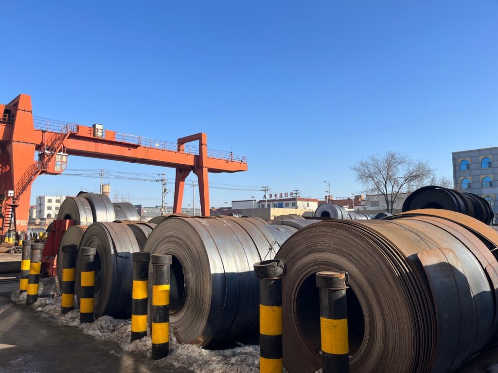
Select a protection strategy as a system
Material thickness and corrosion allowance
Structural thickness must satisfy strength, stability and serviceability before any allowance is added. Where loss is expected and reasonably predictable, the design may reserve sacrificial thickness. This requires a stated exposure model and critical section; it is not a substitute for controlling severe local attack or an unknown aggressive environment.
Hot-dip galvanized coating
Hot-dip galvanizing can provide robust coverage and sacrificial protection for appropriately designed fabrications. The product specification should identify the applicable standard, coating requirements, fabrication category, inspection method, acceptance criteria and repair route. Steel chemistry, thickness, surface condition, venting, drainage and component geometry influence the result.
Paint and duplex systems
A paint system separates the steel from the environment and can be tailored with surface preparation, primer, intermediate and finish coats. A duplex system combines a metallic coating with paint, but performance depends on compatible materials and surface preparation. Specify dry-film thickness by layer, stripe coating where required, environmental conditions, cure, inspection and repair.
Alternative materials or local isolation
Stainless components, sealed details, isolating washers or sleeves may address selected interfaces, but they can introduce galvanic, strength, cost or inspection questions. Review the complete connection, not the isolated item. Fasteners, cut edges and site welds need the same design attention as main members.
Design details that let protection work
Avoid horizontal pockets, narrow unsealed crevices and details that retain mud or water. Provide vent and drain holes required for safe galvanizing and complete coating access. Ensure hollow sections can drain after installation. Keep dissimilar materials separated where the exposure could create galvanic coupling, and prevent runoff from a more noble material concentrating on carbon steel.
At bolted joints, decide whether faying surfaces are coated, masked or prepared for a slip-critical requirement. Check that coating thickness does not prevent fit-up or reduce thread engagement. Define washer and fastener finishes compatible with the members and the tightening method.
At the ground line, account for grading, vegetation, standing water and future soil accumulation. A nominal coating transition positioned exactly at finished grade can become vulnerable if actual levels vary. Use the as-built terrain and support projection when locating transitions and inspection zones.
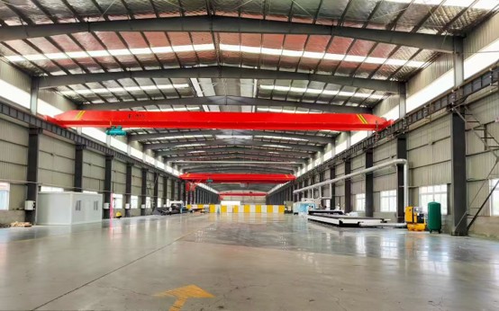
Control fabrication before coating
Complete as much cutting, drilling and welding as practical before final protective treatment. Late modifications create bare edges and local repairs that may not match shop-applied performance. Drawings should mark surfaces with special preparation, masking, no-coat requirements or site-weld zones.
Weld profile, spatter, sharp edges, laminations and surface contamination affect coating continuity. The inspection plan should include preparation acceptance before the coating becomes a concealed record. For galvanizing, confirm venting and drainage with the galvanizer; unsafe sealed cavities or poor drainage are design problems, not shop improvisations.
Protect identification and traceability through the process. If tags are removed for blasting or dipping, use a controlled transfer method. The final coating report must link to the actual batch or component group, not merely state that the factory “uses galvanizing.”
Build a coating inspection and test plan
| Stage | Control | Record | Typical hold point |
|---|---|---|---|
| Material/fabrication release | Grade, dimensions, weld completion, edges, vent/drain features. | Material traceability and fabrication inspection. | Before surface preparation. |
| Surface preparation | Cleanliness, profile and environmental conditions as applicable. | Preparation log and instrument identity. | Before primer or coating. |
| Coating application | Batch, pot life, time between coats, wet/dry-film readings or galvanizing process. | Application report linked to items. | Between critical layers or before dispatch. |
| Final inspection | Coverage, thickness, appearance, adhesion/continuity tests where specified and dimensions. | Inspection map, results and NCR closure. | Before packing. |
| Handling and site work | Damage, repair preparation, compatible materials and cure. | Delivery/site repair report. | Before erection conceals the area. |
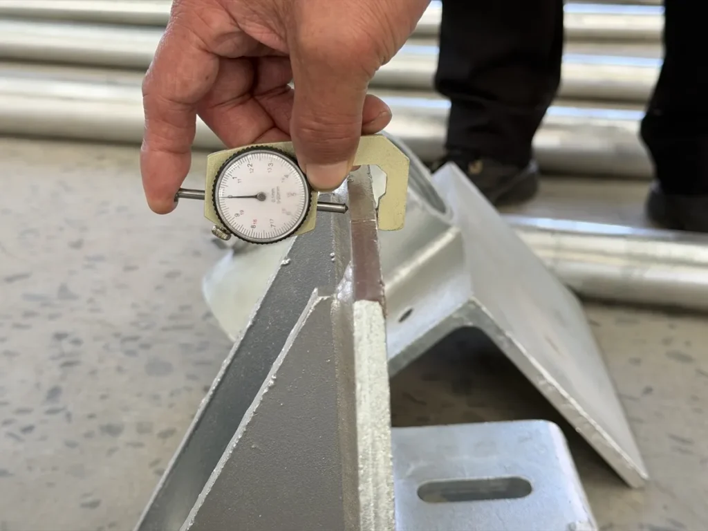
Use calibrated or verified instruments appropriate to the method and substrate. Define sampling locations and quantities before inspection. Averages can hide thin local areas, so acceptance should address both the required distribution and the project standard. Photographs help locate repairs but do not replace measured records.
Protect the system during packing and installation
Coated steel can be damaged by metal banding, forklift contact, dragging, nested movement, trapped moisture and incompatible packing materials. Use separators, edge protection, dry and ventilated packing where required, stable bundles and lifting instructions. Identify drainage orientation and storage limits for long voyages or site exposure.
On site, use approved lifting points and padded slings where needed. Do not place coated members directly in mud or salt-contaminated water. Inspect after unloading and again after erection or driving/screwing. Repair procedures should state preparation, material, minimum conditions, thickness, cure and inspection; repair paint selected by colour alone is not acceptable.
Plan inspection and maintenance from day one
The durability plan should identify inspectable zones, baseline condition, interval, triggers and responsible party. Record coating breakdown, rust staining, section loss, loose fasteners, trapped debris, water paths and ground-line changes. Use consistent photographs and measurement locations so changes can be compared over time.
Prioritise repairs before widespread underfilm corrosion or section loss develops. Clean the area, determine the cause and use a compatible approved system. If damage is structural or buried, the response may require engineering assessment rather than surface repair. Update the asset record with the repair scope and new inspection date.
Project specification checklist
- Exposure zones, site data, design life and maintenance assumption.
- Applicable coating and corrosion standards with edition or project date.
- Base material, nominal thickness and any corrosion allowance.
- Protection system, layer or metallic coating requirements and colours where relevant.
- Detailing rules for edges, cavities, drainage, fasteners, joints and ground line.
- Surface preparation, application conditions, inspection method and sampling.
- Permitted repair materials and procedures for shop, transport and site damage.
- Packing, storage, handling, handover and maintenance records.
Frequently asked questions
Is a thicker galvanized coating always better?
More zinc can increase available sacrificial material, but coating quality, steel chemistry, detail geometry, fit, brittleness risk, exposure and standard requirements all matter. Specify and inspect a suitable system rather than a thickness slogan.
Can galvanized steel be painted?
Yes, when the paint system and preparation are compatible with the galvanized surface. The applicator should follow an approved duplex-system procedure and verify adhesion and cure.
How should buried ground screws be inspected?
Most buried surfaces are inaccessible in service, which is why design assumptions, manufacturing records and installation damage controls are important. Ground-line inspections and selected investigation may be planned according to risk.
What about scratches after installation?
Assess size, depth, location and exposure against the project repair procedure. Clean and repair accessible damage with the specified compatible system; abnormal or buried damage needs engineering review.
Which document proves compliance?
No single certificate proves the whole system. Use material traceability, approved drawings and procedures, batch/application records, inspection results, repair records and final release together.
Define the exposure before requesting a coating price
Send the site environment, design life, component geometry and inspection requirements through the project enquiry form. The Evidence Center explains which controlled records can support a project-specific review.
Corrosion design decision table
| Decision area | Inputs to confirm | Verification output |
|---|---|---|
| Site exposure | Soil resistivity, pH, chlorides, moisture cycle and atmospheric category | Site investigation and corrosion design basis |
| Protection system | Steel grade, zinc/coating system, thickness and detailing | Approved coating specification and inspection plan |
| Acceptance | Sampling locations, measured thickness, repairs and traceability | Coating report linked to the production batch |
Use this table as an enquiry and review checklist. Project design, acceptance criteria and released records remain project-specific.
References, disclosure and change record
References and further verification
- ISO 1461:2022 Hot dip galvanized coatings
- ISO 12944-8 Paint systems for new work and maintenance
- ISO 14713-1 Zinc coating corrosion protection principles
- East Baoyu Quality and Manufacturing
Disclosure: East Baoyu manufactures and supplies products discussed on this website. Structured drafting tools may assist research and editing, but technical claims, project inputs and release decisions require human review.
Version 2.0: Rebuilt with exposure and system-selection tables, detailing and fabrication controls, coating ITP, transport/site protection, maintenance plan, specification checklist, FAQs and reviewed imagery.
View the public Content Change Log · Corrections: info@baolaipipes.com