

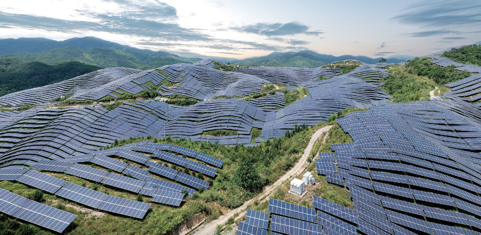
Authorship, review and evidence boundary
- Technical review
- East Baoyu Product & Quality Review Desk
- Reviewed
- 2026-07-23
- Scope
- General engineering and procurement guidance. This article is not a project design, geotechnical report, certificate, warranty, code interpretation or contract requirement.
Evidence basis: Established cable-structure, wind-engineering and PV system verification principles plus East Baoyu product context. Dynamic assessment and testing scope remain configuration-specific.
Read the Editorial PolicyShort answer: a flexible PV mounting system is verified by coordinating cable span, pretension, module and clamp loads, aerodynamic response, support and foundation movement, installation tolerance and long-term tension control. A static strength check is necessary but insufficient; the project must also assess deflection, vibration, fatigue, aeroelastic behaviour, construction sequence and the operating states that change the system’s stiffness.
Flexible systems can cross terrain or create long clear spans with fewer intermediate supports, but that advantage shifts engineering demand into cables, anchors, boundary frames, damping and quality control. The design basis must make those dependencies visible.
Flexible PV verification map
| Design area | Input to control | Response to verify | Evidence |
|---|---|---|---|
| Geometry | Span, sag, module layout, cable spacing, support levels and clearances. | As-installed profile and movement envelope. | Coordinated drawings, survey and tolerance plan. |
| Pretension | Specified force or elongation at a defined temperature and sequence. | Cable stress, stiffness, anchor load and redistribution. | Calculation, calibrated tensioning records and recheck. |
| Wind/aerodynamics | Site wind, turbulence, module gaps, angles and terrain. | Static pressure, vibration, instability and fatigue demand. | Code basis plus appropriate aerodynamic study/testing. |
| Components | Cable, termination, clamp, module frame, support and fasteners. | Strength, slip, local pressure, fatigue and corrosion. | Qualified product data and representative tests. |
| Construction/operation | Sequence, temperature, replacement and maintenance states. | Temporary imbalance, loss of tension and safe access. | Method statements, commissioning and inspection plan. |
Freeze geometry and boundary conditions
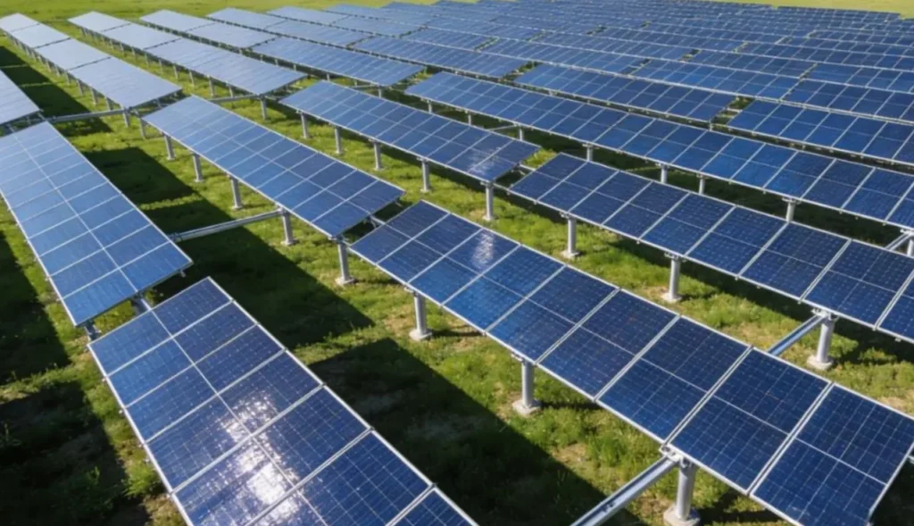
Define clear span, support spacing, cable profile, module dimensions and orientation, gaps, clamp positions, cable-to-cable distance, end anchorage, intermediate restraints and allowable ground clearance. Use actual topography and finished support levels. Small level differences can redistribute tension and change clearance across a long span.
Boundary stiffness matters. A cable model with perfectly fixed ends can underestimate movement if steel frames, bracing, connections or foundations deflect. Include realistic translational and rotational stiffness, erection tolerances and any support settlement. Coordinate these assumptions with the foundation reaction schedule.
Model module mass, cable self-weight, ice or snow where relevant, maintenance load, thermal range and construction states. State whether modules participate structurally; ordinarily, do not assume unintended diaphragm action without verified joints and module approval.
Specify pretension as a controlled state
Pretension establishes geometric stiffness and influences sag, natural frequency, support reactions and module movement. The design should state the target and permissible range at a reference temperature, as well as the measurement or elongation method. Consider cable manufacturing tolerance, seating of terminations, support movement and loss during the first loading cycles.
Tensioning sequence can create asymmetric loads. Define whether cables are tensioned in pairs, by bay or in stages, and identify temporary bracing or exclusion zones. End frames and foundations must resist construction reactions before the complete stabilising system is present.
Temperature changes cable length and force. Include realistic cable and support thermal properties and the range between installation, daily operation and extreme design states. A field value measured at one temperature should be corrected or interpreted using the approved procedure.
Evaluate wind as a dynamic action
Long flexible spans can have low natural frequencies and significant motion. Module edges, gaps, porosity, cable spacing, sag, array position, terrain and turbulence influence aerodynamic loading. Edge and corner zones may differ from internal bays. Check the applicability of conventional static coefficients before using them.
The assessment should screen buffeting, vortex-related response, galloping, flutter or other aeroelastic instability relevant to the configuration. Where code guidance does not cover the geometry, use a suitably designed wind-tunnel, sectional model or validated numerical study. Preserve geometry, turbulence, scaling and damping assumptions with the report.
Dynamic amplification changes cable force, clamp load, support reaction and module acceleration. Verify serviceability and fatigue as well as ultimate strength. A system can remain below cable breaking force yet experience unacceptable module movement, clamp slip or repeated connection damage.
Coordinate cable, module and clamp behaviour
Select cable construction, nominal area, strength, elastic behaviour, relaxation, corrosion protection and termination type. Design terminations for static and cyclic action without damaging strands. Provide bend radii, thimbles or sockets as required and prevent water traps or incompatible-metal contact.
Module clamps must stay within the module manufacturer’s permitted zones and pressure limits. Check local frame deformation, glass clearance, slip and bolt preload over the expected motion range. A clamp proven on a rigid rail may behave differently on moving cables, so representative component or subassembly testing may be required.
Define replaceability. If one module or clamp is removed, determine whether adjacent elements move or cable force redistributes. The maintenance method should keep the remaining structure stable and prevent uncontrolled cable release.
Verify supports, anchors and foundations
End supports can attract large permanent pretension plus environmental loads. Check combined axial force, bending, shear, stability, connection slip and second-order effects. Intermediate frames may have different demands during asymmetric wind, snow, construction or module replacement.
Issue foundation reactions for pretension, ultimate wind, service wind, erection, temperature and credible unbalanced conditions. Include force direction and application height. Foundation displacement feeds back into cable sag and tension, so the structural and geotechnical models should use compatible stiffness assumptions.
For ground screws or piles, trial and verification testing should address the governing tension, compression and lateral components, not only vertical capacity. Survey support position, inclination and elevation before tensioning; forcing a misaligned system into geometry can create hidden preload.
| Observed condition | Potential effect | Required review | Controlled response |
|---|---|---|---|
| Pretension below range | More sag, lower frequency and increased motion. | Temperature, measurement, seating and cable length. | Retension under approved sequence or engineering disposition. |
| Pretension above range | Higher cable, frame and foundation demand. | Instrument, correction, sequence and support movement. | Release/re-tension safely; inspect affected components. |
| Support level outside tolerance | Uneven force and module clearance. | Survey, adjustability and model sensitivity. | Correct support or issue revised geometry/design. |
| Clamp slip or module contact | Local damage and changed load path. | Preload, clamp zone, motion and component condition. | Stop affected bay, replace/repair and verify root cause. |
Use testing to verify the real assembly
Material certificates and component datasheets do not reproduce system interaction. Develop a test matrix from the risk assessment: cable termination capacity and fatigue, clamp slip, module/frame loading, pretension retention, representative bay deformation and dynamic behaviour may all be relevant.
Test boundary conditions should represent the installed detail. Record specimen revision, material batches, assembly torque, pretension, temperature, loading method, instrumentation and failure mode. Do not report only a maximum load; displacement, slip, damage initiation and residual condition can govern design.
Full-scale monitoring or commissioning measurements can confirm natural frequency, damping, tension and movement. Define how measured results update the calculation and what range is acceptable before handover.
Control installation and commissioning
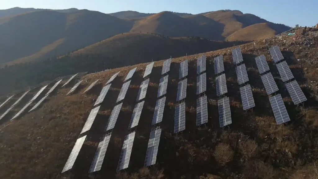
The method should sequence foundations, frames, bracing, cables, initial tension, modules, final tension and survey. Identify temporary stability at every step. Use calibrated tensioning and torque tools, approved measurement points and environmental limits.
Commissioning records should include support survey, cable and termination identity, tension readings with temperature, clamp/fastener checks, sag or profile measurements, clearances, damaged-coating repairs and nonconformance closure. Recheck after seating or a defined initial period where the design requires it.
Protect the system from uncontrolled modifications. Moving a clamp, replacing a cable type, changing a module or adjusting tension can alter dynamics and load distribution. Route changes through engineering review and update the asset baseline.
Use first-bay or first-row release before repeating the installation method. It should verify tool access, tensioning sequence, module handling, measured profile, labels and record forms with the actual crew. Feed lessons into the controlled method, then define production sampling and stop-work triggers. This prevents a systematic geometry or clamp error from being reproduced across many spans before the first formal inspection.
Inspection and maintenance priorities
- Cable tension or sag trend at consistent conditions and locations.
- Broken wires, abrasion, corrosion, termination movement and water retention.
- Clamp position, bolt security, module frame marks and glass clearance.
- Support plumb, bracing, foundation movement and ground erosion.
- Evidence of repeated contact, fretting, vibration or unusual noise.
- Coating damage, debris accumulation and vegetation interference.
After significant wind, snow, impact or maintenance events, inspect the affected zones and preserve observations. An abnormal motion report should be compared with wind conditions, tension and damage; simply tightening components may hide the underlying dynamic problem.
Frequently asked questions
Does higher pretension always reduce wind risk?
No. Higher pretension can increase stiffness and change frequency, but it also increases cable, support and foundation demand. The complete system needs an optimised verified range.
Can static code pressure be used for every flexible PV system?
Only if its applicability to the geometry and dynamic response is demonstrated. Long flexible systems may require additional aerodynamic and aeroelastic assessment.
How is pretension measured on site?
Methods can include calibrated force measurement, approved elongation or other verified procedures. The method, temperature correction, instrument and location must be specified.
What happens if a module must be replaced?
Use a maintenance sequence that controls local stability and cable movement. Replacement module and clamp geometry must match the approved structural interface.
Are ground screw foundations suitable?
They may be, subject to ground conditions, multi-directional reactions, displacement limits, corrosion design and testing. The high permanent anchor forces deserve explicit verification.
Define the span, site and verification boundary
Review the flexible PV mounting system, then submit topography, span concept, module data and wind basis. A credible proposal should identify dynamic-study, testing and foundation inputs still required.
Flexible PV structural input table
| Decision area | Inputs to confirm | Verification output |
|---|---|---|
| Geometry | Span, sag, module arrangement, support levels and clearances | Controlled system layout and survey basis |
| Pretension | Installation state, temperature range, tolerances and losses | Approved tensioning procedure and records |
| Dynamic response | Wind spectrum, damping, modes, stability and serviceability limits | Validated analysis or test method with limitations |
Use this table as an enquiry and review checklist. Project design, acceptance criteria and released records remain project-specific.
References, disclosure and change record
References and further verification
Disclosure: East Baoyu manufactures and supplies products discussed on this website. Structured drafting tools may assist research and editing, but technical claims, project inputs and release decisions require human review.
Version 2.0: Rebuilt with verification and field-disposition tables, boundary/pretension controls, dynamic wind screening, components, supports, testing, commissioning, maintenance, FAQs and reviewed visuals.
View the public Content Change Log · Corrections: info@baolaipipes.com