

Flexible PV Bracket
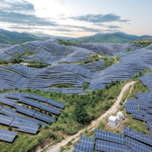
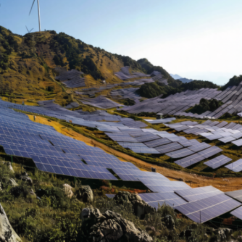
Purpose of this page. Flexible PV mounting uses cables or other tensioned elements between supports to achieve a project-defined span and clearance where conventional tables may be difficult. It explains the engineering and procurement route without treating a catalog example as an approved project model.
Application decision context
Span is only one variable. Pretension, sag, temperature, wind-induced response, snow, module behaviour, support stiffness, anchor reaction, terrain and construction tolerances interact. A published photograph or marketing span cannot establish suitability for another site.
Required project inputs
- Module layout, span, clearance and support coordinates
- Wind, snow, temperature, seismic and dynamic criteria
- Survey, terrain, water, drainage and access constraints
- End-support and anchor ground or structural information
- Tensioning sequence, equipment, measurement and inspection access
Configuration and interface route
Cable arrangement, intermediate supports, end frames and anchors are modelled as one system. Pretension and allowable deflection are linked to temperature and construction stages. Module clamps and electrical routes must accommodate movement without damage or loss of clearance.
Manufacturing and verification plan
The calculation basis and drawings define cable properties, support reactions, tensioning values and acceptance tolerances. Material certificates, termination records, dimensional checks and tensioning logs may form part of the ITP. Dynamic validation or project testing follows the governing specification.
Installation, logistics and site coordination
The construction sequence establishes temporary stability, support erection, cable installation, staged tensioning, module placement and final survey. Weather limits and calibrated tools may be required. Anchor movement, tension variation and damaged terminations need an exception and release process.
Design and supply boundaries
- No universal maximum span is published
- No universal claim of zero earthwork or lower cost is made
- Anchor and end-support design is part of the system
- Inspection and retensioning needs follow the approved O&M plan
Documents to define before release
- System model and calculation basis
- Support, anchor and cable schedule
- Material and termination certificates
- Tensioning method and calibrated-tool record
- Installation survey and exception log
- Inspection and maintenance procedure
The Product Data Center shows how this application connects to the product family and configuration route. Public catalogs support orientation only. The approved calculation, drawing, bill of material, quotation, ITP and contract define the supplied scope. Use the Evidence Center to request the records applicable to the actual order.
Technical data framework
Project-specificFlexible PV Mounting Technical Data Template
Flexible mounting is a project-engineered cable and support system. Span, pretension, deflection, dynamics, anchor reactions and construction sequence must be verified for the actual site.
Required design inputs
- Module layout, clearances, span and support locations
- Wind, snow, temperature, seismic and dynamic criteria
- Survey, terrain, water/drainage and access constraints
- End support and anchor ground/structural information
- Construction sequence, tensioning method and inspection access
Decision boundaries
- Large span is not a fixed product value
- Deflection and vibration require project analysis
- Anchor and end-support reactions may govern feasibility
- Prestress, temperature and erection sequence must be controlled
| Parameter | Published value status |
|---|---|
| Span / support spacing | By analysis and site layout |
| Cable type / area | By structural and durability design |
| Pretension / sag | By approved tensioning schedule |
| End / intermediate supports | By reaction and stability design |
| Anchors / foundations | By site and support reactions |
| Damping / restraints | By dynamic assessment |
| Corrosion protection | By exposure and design life |
| Monitoring / retensioning | By inspection and O&M plan |
Project deliverables
- Structural and dynamic calculation basis
- Support, anchor and cable drawings
- Tensioning method and records
- Material and coating certificates
- Dimensional / final inspection records
- Inspection, monitoring and maintenance plan
Acceptance rule
- Applicable standard and drawing revision identified
- Inspection characteristic, frequency and acceptance criteria defined
- Records linked to the actual batch, item or installation location
- Exceptions and release authority documented
Catalog dimensions and website examples are selection inputs only. The approved drawing, calculation, quotation, ITP and contract define the supplied product.
Request project data sheetStable information architecture
Open Product Data Center Product family → configuration → application → evidence
Configuration route
Fixed mounting, Tracking mounting, Flexible mounting
Application pages
Fixed PV mounting · Solar tracking systems · Flexible PV mounting
Resources and evidence
The public product families are fixed, tracking and flexible mounting. Geometry, member schedules, controls, foundations, coatings and acceptance records are project outputs.