

Authorship, review and evidence boundary
- Technical review
- East Baoyu Engineering Editorial Team
- Reviewed
- 2026-07-29
- Scope
- General engineering and procurement guidance. This article is not a project-specific design, capacity statement, certificate, warranty, code interpretation or contract requirement.
Evidence basis: Official and public references identified in the article, together with original editorial diagrams. Project values and release decisions require qualified review under the applicable project responsibilities.
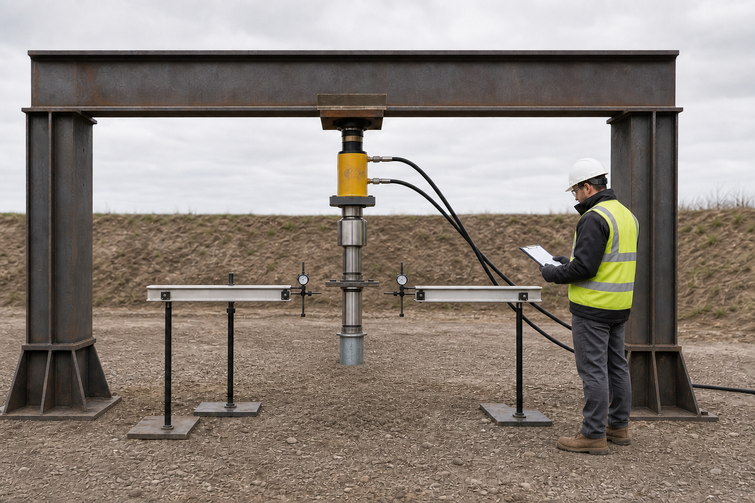
Read the Editorial PolicyA compression test can look orderly and still produce an unusable result. The reaction frame may be stable but the jack may not be coaxial with the test element. The load cell may be calibrated but its serial number may not appear in the field sheet. Movement gauges may show clean values while their reference beam responds to the reaction system. A final curve can therefore look convincing even though the chain between the installed element, applied load, measured movement and approval decision cannot be reconstructed.
This guide begins after the test programme, apparatus design, method statement, loading schedule, safety plan and acceptance basis have been approved. It explains how an EPC or testing team can execute and document a ground screw compression load test without improvising project criteria in the field. The result describes one tested element under recorded conditions; it does not by itself establish uplift, lateral, cyclic, group or long-term performance.
1. Start from the approved test basis
Before mobilization, issue a controlled test pack that identifies the test element, location, installation record, adopted test basis, approved procedure variant, apparatus design, loading and unloading schedule, hold and reading instructions, stop authority, safety controls, acceptance route and required deliverables. Static axial compression methods are not interchangeable: recognized procedures can use different timing and loading patterns and may produce different load-displacement curves. The field team must therefore work from the approved project version rather than from memory or a generic checklist.
The public scope of ASTM D1143/D1143M-26 assigns engineering responsibility for the loading apparatus and test interpretation and notes that project provisions may add requirements. ISO 22477-1:2018 addresses maintained static axial compression testing of a single pile and separates that scope from constant-rate and cyclic tests. Neither public page supplies a universal project load, increment, hold, stop or acceptance value.
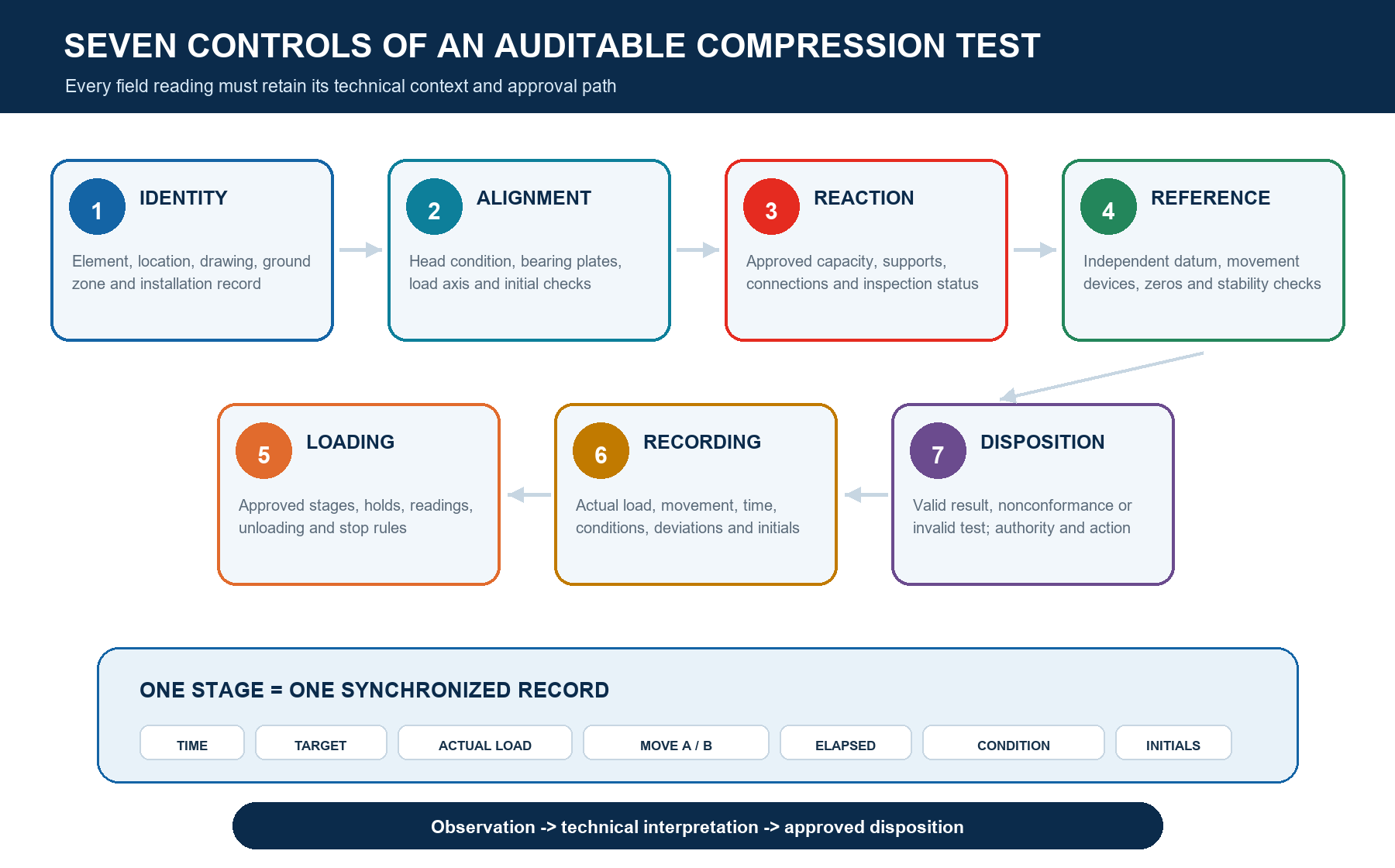
2. Establish the seven-control field chain
Use the seven controls as a readiness and record index. Each control needs an approved input, a field observation and an accountable disposition. A weakness in one link cannot be repaired by adding more detail elsewhere: a precise gauge cannot correct a misidentified test element, and a complete load log cannot prove that the reference system remained independent.
| Control | Field question | Evidence retained |
|---|---|---|
| Identity | Is this the approved test element in the approved condition? | Location, ID, geometry, installation record, date and photographs. |
| Alignment | Is load transferred coaxially without unintended eccentricity? | Set-up checks, centring observations and approved tolerances. |
| Reaction | Can the engineered system apply the sequence without influencing the result? | Design reference, inspection, support condition and monitoring. |
| Reference | Are movement readings independent of test and reaction movement? | Reference layout, supports, gauge locations and stability checks. |
| Loading | Was the approved schedule followed by calibrated equipment? | Instrument IDs, calibration status, commanded and measured load/time. |
| Recording | Can every value be linked to one stage and timestamp? | Synchronized field sheet, photographs, weather and observation log. |
| Disposition | Who decides valid, invalid, nonconforming, repeat or release? | Signed review, deviations, interpretation and authorized decision. |
3. Verify the test element and installation record
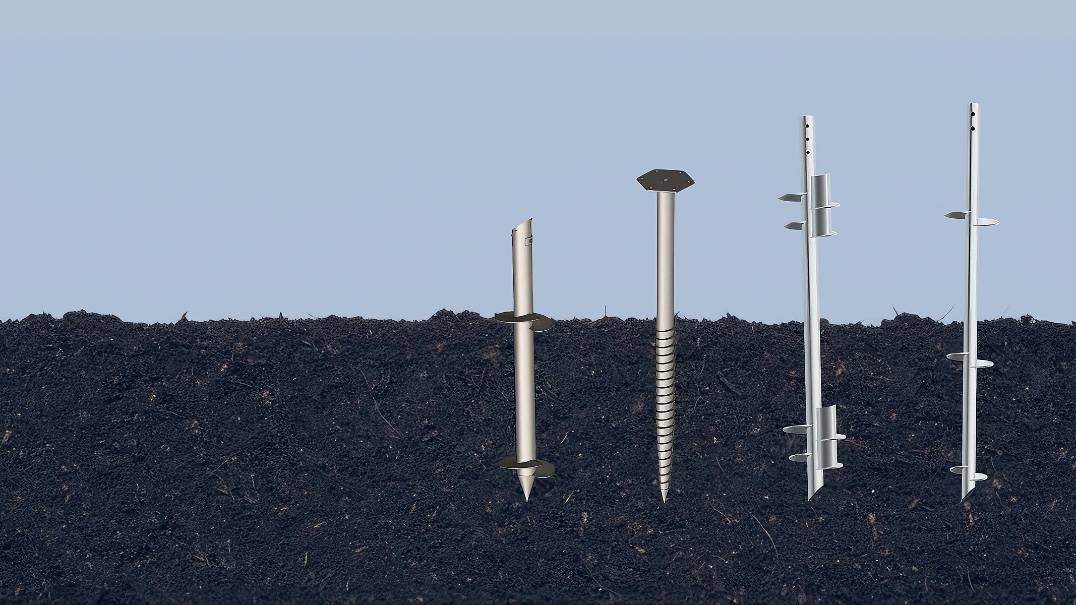
Confirm the element ID against the approved location plan before placing apparatus. Record product designation, shaft and helix configuration where applicable, head detail, length, installation date, final level, inclination or verticality check, installation equipment, operator and ground zone. Retain the raw installation log, including torque data when specified, interruptions, predrilling or refusal events, extensions, damage, corrections and any post-installation modification.
Installation torque can be a useful process observation, but it is not a stand-alone proof of compression capacity. Use the separate East Baoyu guide on Installation Torque and Ground Screw Capacity to keep torque interpretation within a project-calibrated evidence chain. Also retain relevant site-investigation and zoning information from Ground Screw Selection from Site Investigation so the test is not detached from the ground conditions it represents.
4. Inspect the reaction system and aligned load path
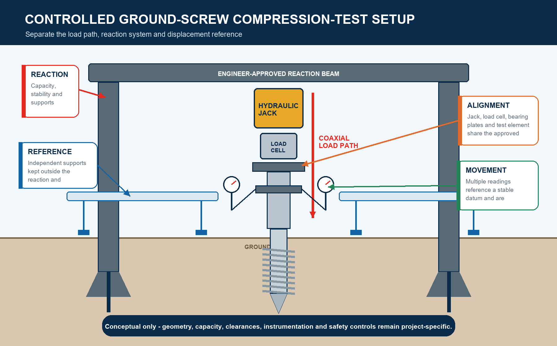
The reaction system, beams, anchors or supports must match the approved engineered arrangement. Before loading, inspect member identity, connections, bearing and support conditions, jack seats, head plate, clearances and any signs of damage or unintended contact. Confirm that the load cell, jack, spherical seating or other approved alignment components form the intended load path. The jack and test-element axis should not be forced into apparent alignment by unstable packing or uncontrolled field modification.
Reaction capacity and geometry are project-specific. This article does not prescribe anchor spacing, beam size, apparatus factor, exclusion distance or allowable movement. Those values belong in the approved design and safety plan. Establish the observation points needed to detect reaction movement, rotation, local bearing distress, leakage or loss of seating. If the field arrangement differs from the approved drawing, stop and obtain the named authority's disposition before applying test load.
5. Build an independent displacement reference
Movement instruments only describe test-element displacement if their reference is stable enough for the adopted method. Place reference supports, beams and gauge mounts as shown on the approved arrangement, protect them from contact, vibration, personnel and weather effects, and document their relationship to the test and reaction system. Take initial readings after the apparatus has settled into its approved pre-load condition and record any reset or zeroing event rather than overwriting it.
Where the approved method uses multiple gauges, retain each raw reading; do not record only an average. Differences between instruments may reveal tilt, eccentricity, local head deformation, a loose mount or reference disturbance. The required gauge number, resolution, range, accuracy, calibration interval and allowable disagreement are project decisions. A reference check before, during and after the sequence is more useful than assuming that a beam remained still because it appeared undisturbed.
6. Confirm load and movement instrumentation
Create an instrument register that links the load cell, pressure transducer or gauge, hydraulic system, displacement indicators, data logger and time source to serial numbers, ranges, units and calibration evidence. Verify that the selected ranges cover the approved sequence without operating near an unsuitable limit. Record which device provides the reported load when more than one indication is present and define how disagreement will be handled.
Public FHWA compression-test documentation illustrates the combined use of a reaction frame, hydraulic jack, load cell, independent reference beam and movement indicators. Another FHWA field example shows calibrated loading and redundant movement observations. These are archived project examples, not universal ground-screw apparatus or sequencing requirements.
7. Complete the pre-test readiness gate
Hold a documented readiness check with the test supervisor, responsible engineer or testing agency representative, safety lead and recorder roles defined by the project. The gate should be completed before the test begins, not reconstructed afterward. Photograph the complete arrangement and key details from fixed viewpoints so later reviewers can relate the record to the approved drawing.
| Readiness area | Minimum confirmation before loading |
|---|---|
| Controlled basis | Current method, apparatus design, sequence, acceptance route and safety plan are present. |
| Element | ID, position, installation record, head condition and test condition match the authorization. |
| Apparatus | Members, supports, connections, seating, alignment and clearances match the approved arrangement. |
| Reference | Supports and gauges are protected, stable, readable and independently checked. |
| Instruments | IDs, ranges, units, calibration evidence, zero readings and time source are recorded. |
| People / safety | Roles, communications, exclusion control, stop authority and emergency arrangements are active. |
| Record | Field sheet, stage numbers, photo convention, deviation log and signatures are ready. |
8. Run the approved loading sequence without improvisation
Assign one person to control loading and one to control the record, even when the same organization provides both. At every approved stage, approach the commanded load in a controlled manner, stabilize it as required by the method, announce the stage and synchronize the load, movement, time and observation entries. Use measured load rather than an unverified pump indication. If a stage is overshot, a reading is late or the load drifts outside the approved control band, record what happened and follow the pre-agreed deviation route.
Do not invent an extra load, shorten a hold, skip a reading or change the unload path to recover lost time. Even a technically plausible field change can make the result incomparable with the approved basis. Stop criteria may include apparatus behavior, movement, loss of load control, safety observations or project limits, but the actual criteria and authority must come from the controlled method statement.
9. Record each stage as a synchronized data row
A useful field sheet preserves raw observations before interpretation. One stage row should connect the stage identifier, commanded load, measured load, stage start, reading time, elapsed time, each movement channel, calculated value if used, reaction or reference observations, weather or disturbance notes and recorder initials. Keep units in column headings and retain full instrument precision; rounding for a report should not replace the raw values.
| Record block | Fields to retain | Control purpose |
|---|---|---|
| Identity | Project, location, element ID, test date, drawing/method revision. | Prevents results being detached from the tested configuration. |
| Stage / load | Stage ID, command, measured load, application time and drift. | Shows whether the approved loading path was achieved. |
| Movement | Timestamp and every raw gauge or sensor reading with units. | Preserves tilt, disagreement and reference evidence. |
| Conditions | Weather, temperature if required, disturbances and apparatus observations. | Supports interpretation of anomalies and interruptions. |
| Control | Recorder, checker, photo ID, deviation reference and initials. | Makes corrections, review and accountability traceable. |
Correct mistakes visibly: preserve the original entry, identify the correction, state the reason and add the responsible initials or electronic audit trail. Never erase an unfavorable reading or silently replace it with a later value. Raw field sheets, data logger exports, calibration records and photographs should be protected from later overwriting and named consistently with the test element and revision.
10. Control stops, anomalies and invalid tests
Treat safety stops, load-control problems, excessive reaction movement, gauge disagreement, reference disturbance, power loss, hydraulic leakage, unexpected head rotation and missed readings as recordable events. Stop or hold the test according to the approved rules, capture the state before disturbing the apparatus and notify the authority named in the method. Do not decide validity only after seeing whether the result appears favorable.
| Observed condition | Immediate record | Disposition route |
|---|---|---|
| Valid result misses criterion | Complete raw data and condition record. | Report as a nonconformance for authorized engineering decision. |
| Reference or instrument compromised | Time, stage, channels, photos and suspected cause. | Qualified reviewer decides validity, repeat or usable scope. |
| Apparatus differs from approval | Mark-up, dimensions, affected stage and stop time. | Do not continue until the designated authority accepts a route. |
| Safety stop | Trigger, personnel action, equipment state and communications. | Follow the project safety plan before any technical restart decision. |
| Correction or retest | Original record plus new authorization and unique record ID. | Never overwrite or relabel the original test as though it did not occur. |
11. Unload, capture rebound and close field activities
Follow the approved unloading sequence and reading times with the same discipline used during loading. Retain each movement channel through unloading and any specified final observation period. Rebound is part of the response history, but this article does not assign a universal rebound ratio or acceptance meaning. Record residual movement, load-cell return, zero checks and any instrument behavior that affects confidence.
Before dismantling, complete final photographs, reference checks, apparatus inspection and recorder/supervisor sign-off. Mark whether the element will remain, be removed, be examined or be protected pending disposition. Site restoration, reuse and production release require separate authorization. Keep the work area controlled until stored energy, suspended components and hydraulic pressure have been managed under the safety plan.
12. Separate observation, interpretation and release
The field team observes and records. The designated technical reviewer validates the test basis and data quality, calculates approved reductions, plots load-displacement and time-dependent behavior where required, identifies limitations and interprets the result. The approving engineer or project authority then decides acceptance, nonconformance, further testing, design change or release. These roles may sit within one organization, but their decisions should remain explicit.
The public scope of ICC-ES AC358 (24) provides helical-pile evaluation context for full-scale axial testing, installation records and coaxial loading. It is not automatically the field acceptance specification for every ground screw project. The adopted code, contract, test standard and project professionals remain controlling.
13. Assemble the auditable test package
Issue one indexed package rather than a curve separated from its evidence. The report should identify the project and element, adopted basis, purpose and limitations; describe the ground and installation context; show the approved and as-tested apparatus; list instruments and calibration status; reproduce raw and processed data; explain calculations; log deviations; include photographs; and carry the responsible reviews, interpretation and final disposition.
| Package section | Auditable content |
|---|---|
| Authority / scope | Request, test basis, revisions, procedure variant, decision purpose and exclusions. |
| Element / ground | Location, configuration, installation record, ground zone and relevant site conditions. |
| Apparatus / safety | Approved design reference, as-tested arrangement, inspection and recorded controls. |
| Instruments / raw data | Register, calibration evidence, zeros, synchronized sheets, logger exports and photos. |
| Analysis / limitations | Approved calculations, plots, anomalies, validity statement and bounded interpretation. |
| Disposition | Acceptance or nonconformance route, action owner, signatures, dates and controlled release. |
Compression results should not be copied to every production element without an approved representativeness argument. Ground variability, product configuration, installation method, test timing and construction condition may change. Link the result back to the programme's zones, quantities and decision rules, and keep separate evidence for uplift, lateral or other response modes when those are design requirements.
14. What to send East Baoyu
For a supplier engineering review, send the controlled project basis and the exact question to be answered. Useful inputs include the ground investigation and zoning, ground screw schedule and drawings, design actions and combinations, installation records, approved test method, apparatus drawing, instrument register, raw field data, photographs, deviations, preliminary report and the decision owner. Remove ambiguity about units, coordinate references and revisions before transmitting the package.
| Submission | Minimum content |
|---|---|
| Project basis | Location, jurisdiction, standards, design stage, loads and requested decision. |
| Ground / element | Investigation, zones, water conditions, product configuration and installation record. |
| Test controls | Approved method, sequence, apparatus, safety boundary and responsible authorities. |
| Evidence | Instrument/calibration register, raw synchronized data, photos and deviation log. |
| Review request | Questions, required output, deadline, revision and downstream decision owner. |
Review East Baoyu's Screw Piles, Quality & Manufacturing and Certification & Evidence Center pages before requesting a project-specific response. Supplier-side review can clarify product configuration, drawings and manufacturing evidence; it does not replace the project geotechnical/structural engineer, testing agency or authority.
Request an engineering review
Send the approved test basis, ground screw identity, apparatus arrangement, instrument register, raw synchronized records, photographs and specific review question. East Baoyu can assess supplier-side interfaces and evidence gaps within an agreed scope; the project's designated professionals retain responsibility for apparatus approval, test validity, interpretation, acceptance and construction release.

Questions? Chat with East Baoyu on WhatsApp. Fast reply on capacity, price, configuration and available product videos.
Open WhatsApp: +86 130 1228 3281
| Contact | Official detail |
|---|---|
| info@eastbaoyu.com | |
| Phone | +86 22 28352066 |
| +86 130 1228 3281 | |
| Website | https://eastbaoyu.com/contact/ |
Email the engineering review package: info@eastbaoyu.com
Frequently asked questions
What does a ground screw compression load test demonstrate?
It links applied axial compression load to measured movement for the identified element and recorded test conditions under the adopted procedure. Interpretation and acceptance remain project decisions. The test does not automatically prove uplift, lateral, cyclic, group or long-term performance.
Can installation torque replace a compression load test?
No. Torque is an installation observation whose relationship to capacity depends on product, equipment, ground and project-specific correlation. Where the approved programme requires a compression test, torque records support identity and context but do not replace measured load-movement evidence.
Who should approve the reaction system and test method?
Use the qualified professionals and authorities named by the adopted standard, contract and jurisdiction. The apparatus, reaction and support system require project-specific engineering; the procedure, interpretation and acceptance route also need explicit authorized ownership.
Why must the movement reference be independent?
If a gauge reference responds to the reaction system, test element, vibration or contact, its reading can mix true element movement with reference movement. The approved layout and stability checks must demonstrate how the reference is protected and how disturbances are identified.
What should happen when a gauge or load reading looks wrong?
Preserve the value, record the time, stage, channel, conditions and suspected cause, then follow the approved hold or stop route. A qualified reviewer should decide whether the test remains valid, has a bounded usable scope or requires a repeat. Do not silently replace the original reading.
What records should accompany the final compression-test curve?
Include the approved basis, element and installation identity, ground context, apparatus and reference arrangement, instrument/calibration register, raw synchronized readings, photographs, deviations, calculations, limitations, technical review and signed disposition.
Related East Baoyu resources
Screw Piles | Ground Screw Selection from Site Investigation
Installation Torque and Ground Screw Capacity | Corrosion Design for Ground Screws, Solar Mounting and Structural Steel
Screw Piles versus Concrete Foundations | Quality & Manufacturing
Certification & Evidence Center | Product Documents & Buyer Guides
Engineering Research & Methods | Engineering Articles
References and scope notes
Sources were checked on 28 July 2026. Public scopes and examples are paraphrased; this article does not reproduce paid procedural clauses or prescribe universal test loads, increments, holds, reaction spacing, instrument specifications, stopping criteria or acceptance limits. It is not a project method statement, apparatus design, safety plan, geotechnical interpretation or construction release.
ASTM D1143/D1143M-26 – Deep Foundations Under Static Axial Compressive Load | ISO 22477-1:2018 – Testing of geotechnical structures: pile load test by static axially loaded compression
ICC-ES AC358 (24) – Helical Pile Systems and Devices | FHWA-HRT-05-159 Chapter 4 – Static compression test example
FHWA-HRT-04-043 Chapter 6 – Calibrated loading and movement measurements
References, disclosure and change record
References and further verification
- https://store.astm.org/d1143_d1143m-26.html
- https://www.iso.org/standard/70807.html
- https://eastbaoyu.com/installation-torque-and-ground-screw-capacity/
- https://eastbaoyu.com/ground-screw-selection-from-site-investigation/
- https://www.fhwa.dot.gov/publications/research/infrastructure/geotechnical/05159/chapter4.cfm
- https://www.fhwa.dot.gov/publications/research/infrastructure/structures/04043/06.cfm
- https://icc-es.org/wp-content/uploads/acceptance-criteria/AC358.pdf
- https://eastbaoyu.com/screw-piles/
- https://eastbaoyu.com/quality/
- https://eastbaoyu.com/evidence-center/
- https://wa.me/8613012283281
- https://wa.me/8613012283281?text=Hello%20East%20Baoyu%2C%20I%20would%20like%20an%20engineering%20review%20of%20a%20ground%20screw%20compression%20load%20test%20package.
- https://eastbaoyu.com/corrosion-design-ground-screws-solar-steel/
- https://eastbaoyu.com/screw-piles-vs-concrete-foundations/
- https://eastbaoyu.com/downloads/
- https://eastbaoyu.com/research-methods/
- https://eastbaoyu.com/articles/
- https://eastbaoyu.com/contact/
Disclosure: East Baoyu manufactures and supplies products discussed on this website. Structured drafting tools may assist research and editing, but technical claims, project inputs and release decisions require qualified review under the applicable project responsibilities.
Version 1.0: Initial scheduled publication in the East Baoyu engineering knowledge-base batch.
View the public Content Change Log · Corrections: info@baolaipipes.com