

Authorship, review and evidence boundary
- Technical review
- East Baoyu Product & Quality Review Desk
- Reviewed
- 2026-07-23
- Scope
- General engineering and procurement guidance. This article is not a project design, geotechnical report, certificate, warranty, code interpretation or contract requirement.
Evidence basis: Cited geotechnical and helical-system guidance, established design/installation control principles, and East Baoyu controlled product context. Project values require qualified geotechnical and structural review.
Read the Editorial PolicyShort answer: select a ground screw from a site investigation by converting the ground model, structural actions, durability exposure and installation constraints into a controlled trial-and-verification plan. A catalogue diameter or nominal “capacity” is not enough. The selected geometry must be installable through the actual strata, able to transfer compression, tension, shear and moment within movement limits, and supported by project-specific acceptance evidence.
This workflow is intended for early design, tender clarification and production release. It identifies what the geotechnical engineer, structural designer, installer, manufacturer and buyer each need to close before a ground screw becomes an approved foundation component.
The selection route at a glance
| Stage | Question to close | Typical output | Release condition |
|---|---|---|---|
| 1. Ground model | Which strata, groundwater, obstructions and variability control installation and resistance? | Interpreted geotechnical model with zones and uncertainty. | Design and trial assumptions are traceable to investigation data. |
| 2. Load path | What compression, tension, shear, moment and cyclic actions reach each support? | Factored and service reaction schedule with interface geometry. | Load combinations and movement limits are approved. |
| 3. Product concept | Which shaft, helix, toe, head and corrosion configuration is credible? | Preliminary pile schedule and calculation basis. | Geometry can be manufactured, installed and connected. |
| 4. Field confirmation | Does the system install as assumed and show the required response? | Trial logs, verification tests and adjusted zone rules. | Acceptance criteria and exception routes are approved. |
| 5. Production control | How will every installed pile be identified and accepted? | ITP, method, calibration plan and as-built register. | Records can link product, location, installation and disposition. |
Build a ground model for installation as well as design
Start with the site investigation report, borehole or test-pit logs, laboratory data, in-situ test results, groundwater observations, topography and site history. Separate observed facts from interpretation. The design model should identify characteristic strata and parameters, while the installation model should also flag coarse fill, cobbles, buried foundations, hard layers, very soft zones, seasonal access and underground services.
Investigation spacing is never a guarantee that every pile point is identical. Divide a large site into geotechnical or installation zones and record the uncertainty between investigation locations. On sloping or made ground, the critical change may occur over a short distance. A zone plan lets the team assign trial locations, product options and exception rules intelligently.
Groundwater matters to durability and construction. Record the observed level, likely variation and whether the ground is aggressive to steel or protective coatings. If chemical data are limited, state the assumption and decide whether additional sampling is needed. Do not convert one laboratory result into a site-wide exposure category without considering the sampling location and ground variability.
Translate structural reactions into foundation demand
Issue reactions at the actual connection point, with coordinate directions and load-combination labels. Ground screws for fixed-tilt solar, single-axis trackers, cabins or light structures may experience very different ratios of uplift, lateral load and moment. Eccentric heads and above-ground projection add bending that is easy to miss when only vertical loads are quoted.
Serviceability requirements should be set by the supported system. Tracker drive alignment, module-table geometry, doors, cladding and utility connections may be more movement-sensitive than the foundation’s ultimate limit state. Define acceptable settlement, uplift displacement, lateral deflection and rotation, including differential values between adjacent supports.
Consider erection and temporary conditions. A partially built frame can have a different wind load path, and installation equipment may impose local ground pressure or access needs. Accidental impact, scour, frost, expansive soil, seismic action or cyclic wind loading should be screened where relevant to the site and governing design basis.
Screen the ground screw family
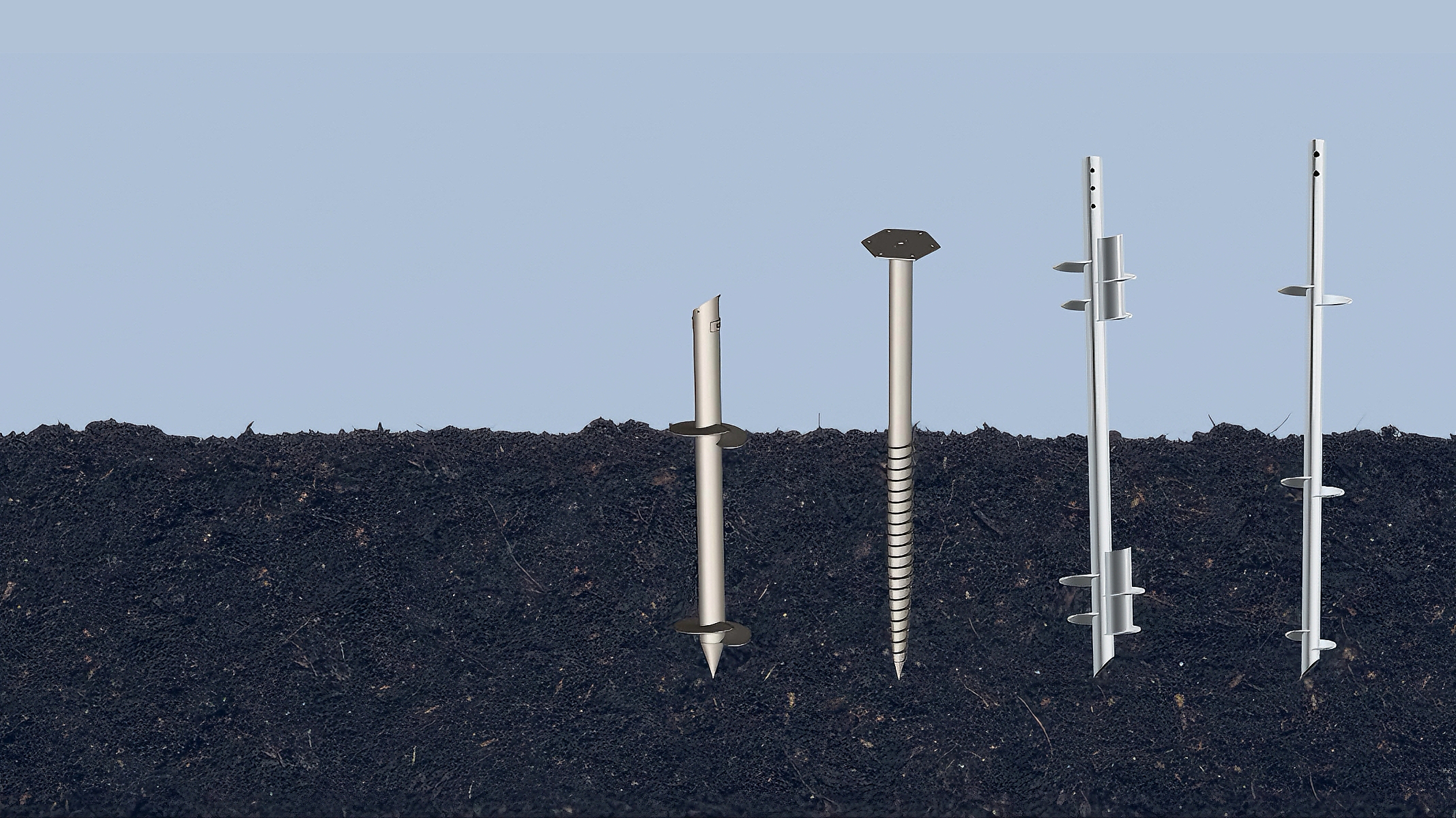
The preliminary choice includes shaft diameter and wall, helix or flight geometry, toe, length, head connection, extension strategy, material grade, weld detail and corrosion protection. Each feature affects more than one function: a larger helix may improve resistance in a suitable stratum but increase installation demand; a longer above-ground projection may help terrain adjustment but increase bending and deflection.
Use calculation to screen compression, tension, lateral and structural resistance, but keep geotechnical assumptions visible. If the concept relies on a specific bearing layer, the installation and termination rule must demonstrate that the layer is reached. If a shaft or helix could buckle, yield or be damaged before the target zone, “more torque” is not a safe response.
The connection head should match the supported steelwork and tolerance strategy. Define hole pattern, plate thickness, slotting, bolt grade, weld scope, drainage, coating repair and adjustment range. The head is part of the structural load path, not a generic accessory to be selected after pile installation.
Plan trial installation before production
Place trials in representative and adverse zones, not only beside the easiest access road. The plan should state candidate pile types, target depths, equipment configuration, measurement method, logging interval, verticality tolerance and stop criteria. It should also describe what happens after refusal, unexpectedly low resistance, excessive depth, visible damage or deviation.
Record installation response continuously enough to understand changes with depth. A final torque value without depth history can hide a transient obstruction or a loss of response below the peak. Equipment calibration, operator method, rotational speed and down-pressure can affect readings, so the trial record must identify the setup.
Use load or other verification testing under an approved method to check the design and establish production acceptance. The test arrangement needs adequate reaction capacity, calibrated instrumentation, load steps, hold periods, displacement readings and a pre-agreed criterion. Select compression, tension and lateral tests according to the governing actions rather than repeating one convenient test type.
Convert trial results into zone rules
| Observed field condition | Engineering review | Possible controlled response | Do not do |
|---|---|---|---|
| Early refusal | Check obstruction, hard layer, geometry, equipment capacity and achieved resistance. | Relocate within tolerance, predrill if approved, change toe/geometry, or use an alternate foundation. | Force installation beyond structural or equipment limits. |
| Low response at design depth | Review ground variation, depth, measurement and required resistance. | Extend to an approved stratum, change geometry, increase test scope or redesign the supported system. | Accept a nominal depth without evidence. |
| Excessive inclination | Assess connection fit, bending, group effects and construction cause. | Correct if permitted, replace, or issue an engineered concession. | Pull the head into position using the frame without review. |
| Unexpected coating damage | Identify damage depth, exposure and repair accessibility. | Apply approved repair above ground or replace/assess buried damage. | Hide damage with unqualified paint. |
Define a production acceptance plan
The approved method should list the product schedule by zone, plant and tooling, survey control, operator checks, calibration validity, permitted weather or access limits, installation parameters, termination rule, inspection frequency, test frequency and escalation path. It should be practical enough for the field team to follow and specific enough for an independent reviewer to audit.
Give each foundation a unique location or asset identifier. Link that identifier to the pile batch, product revision, installation date, depth, inclination, measured response, operator or rig, test status and any nonconformance. Where one record covers a group, define the group boundary so traceability is not lost.
Verification frequency should reflect design risk, variability and the maturity of the correlation—not a generic percentage copied from another project. Increase testing where the ground changes, the installation response is unusual or the consequences of movement are high. Document the engineering basis for any reduction after stable production performance is demonstrated.

Control durability and the ground-line detail
Define the exposure from soil, groundwater, atmosphere and any transition zone at ground level. Select material thickness, metallic coating, paint system, corrosion allowance or other protection using the project design life and maintenance access. The most severe local detail may be the ground line, a trapped-water head connection or a site where grading changes after installation.
Manufacturing and installation controls protect durability. Specify coating thickness and inspection, handling and packing, acceptable repair method, welding sequence, drainage and separation from dissimilar metals where relevant. An attractive general coating certificate does not prove that the delivered pile geometry, batch and repaired areas meet the project requirement.
Minimum project input checklist
- Site location, layout, topographic survey and access constraints.
- Geotechnical report, logs, laboratory data, groundwater and buried-service information.
- Foundation reactions, combinations, coordinate system and serviceability limits.
- Connection geometry, tolerances, finished levels and allowable adjustment.
- Design life, corrosion exposure, maintenance and decommissioning requirements.
- Applicable standards, authority requirements and required design deliverables.
- Trial installation, verification testing, production QA and handover expectations.
- Programme, quantities, work fronts and commercial responsibility boundaries.
Common selection errors
Warning signs include a proposal based only on superstructure weight, one “safe working load” with no load direction, a pile length unrelated to the ground profile, torque treated as capacity without calibration, no rule for refusal, and corrosion protection described only as “galvanized.” Another warning is a quotation that includes production piles but excludes trials, tests, setting-out, equipment mobilisation or as-built records.
A robust proposal clearly distinguishes preliminary assumptions from approved inputs. It states who completes geotechnical and structural design, which documents control manufacture and installation, and what new information could change quantity or price.
Frequently asked questions
Can one ground screw type be used across the whole site?
Sometimes, but only when loads, levels and ground response are sufficiently consistent. Large or variable sites often benefit from controlled zones or an approved small family of pile lengths and geometries.
How many boreholes are required?
There is no universal number. Investigation scope should reflect site size, geology, variability, structure sensitivity and local requirements. The geotechnical professional should design the investigation and identify residual uncertainty.
Is deeper always better?
No. Extra depth can increase material, installation demand and bending without improving the governing resistance. The pile must engage the intended ground and satisfy structural, geotechnical and serviceability checks.
What if trials do not match the design assumption?
Pause the affected work front, verify records and equipment, update the ground interpretation, then issue an approved response. That may involve a different geometry, depth, installation method, test scope or alternate foundation.
Where does torque fit in the workflow?
Torque is an installation measurement that may support acceptance when a justified relationship and control method exist. See Installation Torque and Ground Screw Capacity for the detailed limitations.
Preparing the multidisciplinary input package? Use the ground screw design input checklist for EPC and procurement teams to control the project basis, loads, interfaces, durability, installation, testing, QA and programme before selecting or releasing a pile schedule.
Turn site data into a controlled pile schedule
Review the ground screw product family and submit the ground report, loads and layout. The next step should be a documented assumptions register and trial route—not an unsupported product code.
Ground screw selection table
| Decision area | Inputs to confirm | Verification output |
|---|---|---|
| Ground model | Stratigraphy, groundwater, obstructions and corrosivity | Site investigation report and interpreted design profile |
| Screw configuration | Shaft, helix, length, connection and installation equipment | Selection note linked to the design actions |
| Field confirmation | Trial installation, torque record and load-test plan | Approved test results and acceptance criteria |
Use this table as an enquiry and review checklist. Project design, acceptance criteria and released records remain project-specific.
References, disclosure and change record
References and further verification
- FHWA GEC 5: Evaluation of Soil and Rock Properties
- ICC-ES AC358: Helical Systems and Devices
- East Baoyu Ground Screw Product Data
Disclosure: East Baoyu manufactures and supplies products discussed on this website. Structured drafting tools may assist research and editing, but technical claims, project inputs and release decisions require human review.
Version 2.0: Rebuilt around a five-stage engineering route with selection and exception tables, ground/structural inputs, trial installation, zone rules, durability, production records, FAQs and project-specific next steps.
View the public Content Change Log · Corrections: info@baolaipipes.com