


Authorship, review and evidence boundary
- Technical review
- East Baoyu Product & Quality Review Desk
- Reviewed
- 2026-07-28
- Scope
- General engineering and procurement guidance. This article is not a project structural design, foundation design, capacity statement, certificate, warranty, code interpretation or contract requirement.
Evidence basis: IEC PV module and tracker qualification references, ASCE load-basis overview, DOE and NREL procurement guidance, ISO atmospheric-corrosivity guidance, and an original East Baoyu five-gate input-control framework. Project values require qualified engineering review.
Read the Editorial PolicyShort answer: a solar mounting package is ready for engineering only when the project team has controlled the module, mounting architecture, site geometry, environmental actions, foundation interfaces, durability basis, scope boundary and release status. Early estimates may use declared assumptions, but fabrication and installation require approved inputs linked to one revision baseline. The five-gate checklist below helps EPC and procurement teams keep those boundaries visible.
The fastest way to make a solar mounting quotation unreliable is to request steel tonnage or a unit price before the project has one coordinated design basis. A module datasheet alone is not enough. The supplier needs to know which decision the package supports, how the site is zoned, which actions apply, what the layout and interfaces require, and which ground and durability conditions govern.
Use a release ladder instead of one universal checklist
A package is not simply complete or incomplete. It may be adequate for a screening estimate and still be unsuitable for detailed design. It may support calculations but still lack the approved geometry, tolerances and inspection plan needed for production. The practical question is: which output is being released, and what minimum inputs make that output defensible?
The five gates below separate feasibility, quotation, engineering, manufacture and installation. Procurement should state the current gate in the request and require every offer, drawing and calculation to reference the same input revision.
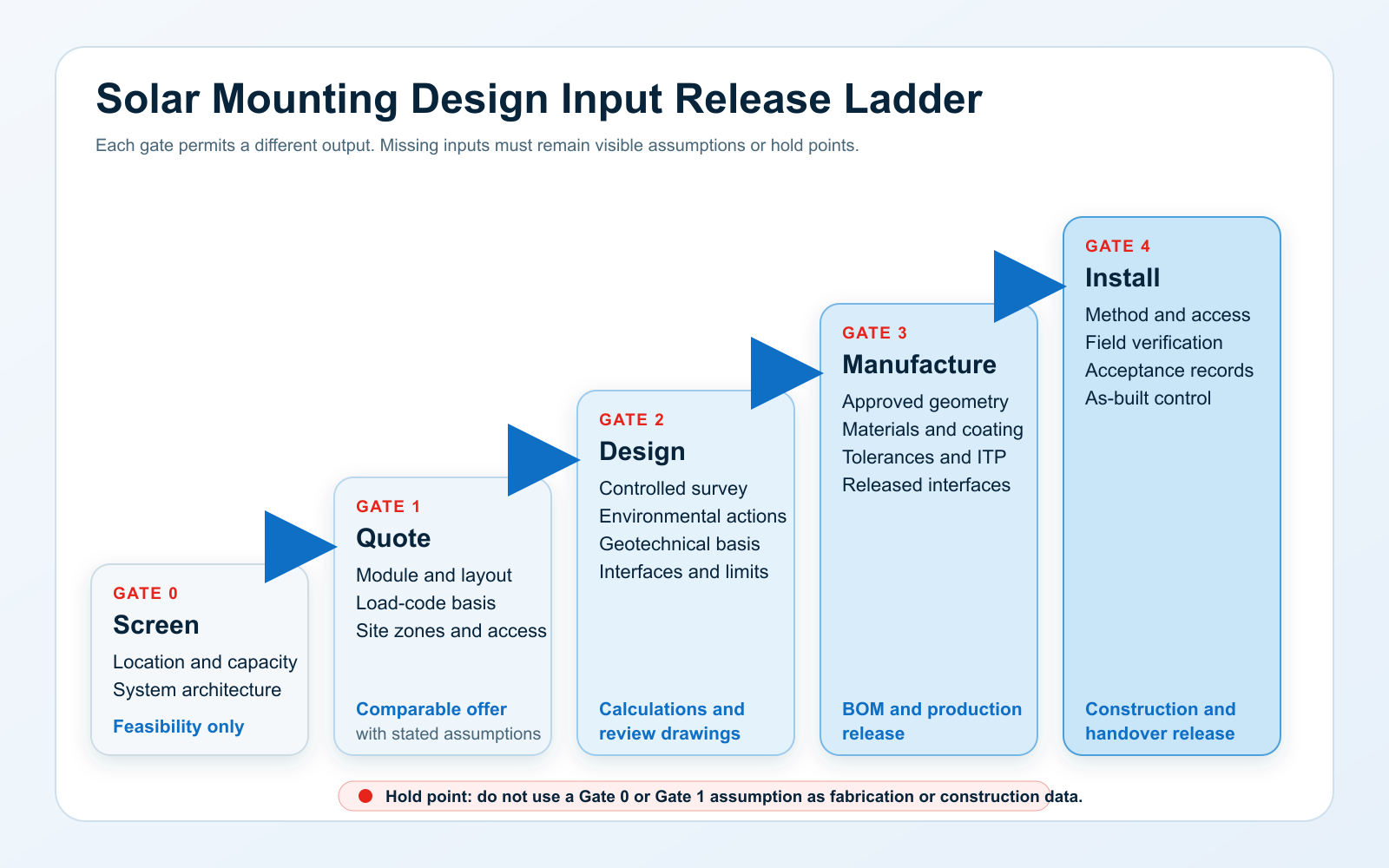
| Gate | Purpose | Minimum controlled baseline | Permitted output | Stop condition |
|---|---|---|---|---|
| 0 — Screen | Feasibility and option range | Location, target capacity, site type, module envelope and likely mounting architecture | Budget range and data request | No product or foundation guarantee |
| 1 — Quote | Comparable supplier offer | Named module, layout concept, load-code basis, site zones, scope and stated assumptions | Priced offer, options, exclusions and preliminary quantities | Uncontrolled module, layout or code inputs |
| 2 — Design | Engineering review | Survey, environmental parameters, geotechnical basis, interfaces, durability and acceptance criteria | Calculations, reactions and review drawings | Conflicting sources or missing governing parameters |
| 3 — Manufacture | Production release | Approved geometry, materials, coating, tolerances, BOM, ITP and revision baseline | Shop drawings and manufacturing release | Open change affecting fit, strength or quantity |
| 4 — Install | Construction and handover | Method, access, field verification, hold points, acceptance records and as-built control | Installation release and dossier | Unresolved site variance or missing acceptance route |
Freeze the module and mounting architecture first
The selected module and mounting concept drive geometry before the first rack member is sized. Record the exact module manufacturer, model and datasheet revision, not only rated power. The controlled package should include dimensions, mass, frame geometry, approved clamping zones or mounting holes, orientation limits, connector and cable locations, grounding provisions, mechanical-load information and the applicable installation manual.
Module qualification does not establish the project mounting design by itself. IEC 61215-2:2021 addresses PV module design-qualification test procedures, while IEC 61730-1:2023 covers module safety qualification. The project team must still verify that attachment method, design actions, support spacing and installation details stay within the module manufacturer’s approved configuration.
Name the system architecture at the same time: fixed tilt, single- or dual-axis tracker, flexible cable-supported mounting, rooftop, carport or another defined arrangement. A tracker package needs its rotation envelope, stow philosophy, drive layout, power and communication interfaces, fail-safe position and controller responsibilities. IEC 62817 provides design-qualification procedures for trackers, but it does not replace site-specific structural and foundation design.
For architecture selection and topic-specific detail, use East Baoyu’s solar mounting systems overview, fixed-versus-tracking comparison, tracker wind and stow coordination guide and flexible mounting verification guide.
Convert the site into a controlled layout basis
A usable site package is more than a boundary polygon. It establishes a coordinate system, datum, survey revision and zones that every discipline can reference. The layout should show array blocks, table or tracker axes, tilt, azimuth, row pitch, lowest and highest module edges, internal roads, piling access, inverter and equipment pads, cable corridors, drainage paths, setbacks, exclusion zones, overhead constraints and known underground services.
For sloping or irregular ground, state whether the concept uses grading, stepped rows, terrain following or another controlled geometry. Provide permitted longitudinal and cross-slope envelopes, pile or post reveal limits, table-to-table tolerance assumptions and any restriction on module twist or frame alignment. Do not treat a yield-model layout as automatically released civil or structural geometry; name the owner who converts the energy layout into a constructible setting-out model.
The U.S. Department of Energy’s FEMP technical-specification resources use array type and site-specific needs to build procurement requirements. NREL’s photovoltaics work specification also calls for checking ground area, slope, stormwater accommodation, soil conditions, subsurface infrastructure, equipment layout and manufacturer requirements. These are coordination inputs, not generic supplier defaults.
Issue environmental actions as parameters, not labels
Terms such as “high wind,” “snow area” or “seismic site” are not calculation inputs. The design basis must name the governing code and edition, national annex or local modification, authority having jurisdiction, risk or reliability category, design working-life basis and required load combinations. It must also define units, sign convention, coordinate directions, load application point and whether reported actions are characteristic, allowable, ultimate, serviceability or another stated basis.
- Wind: basic wind parameter, averaging time, return period or reliability basis, exposure or terrain category, topographic factor, array height, directionality, shielding policy, dynamic considerations and tracker stow state where relevant.
- Snow and ice: ground snow parameter, exposure and thermal assumptions, balanced and unbalanced cases, drifting or sliding snow, array geometry, maintenance assumptions and combinations with wind where the code requires them.
- Seismic: site class or soil-dependent parameters, mapped hazard values, importance basis, structural-system assumptions, equipment interaction and foundation-interface requirements.
- Other actions: dead load, erection and maintenance loads, temperature range, flooding or scour, rain, atmospheric ice, settlement, accidental actions and project-specific operational cases.
For U.S.-based projects, ASCE/SEI 7-22 covers multiple hazards together with load combinations. Other countries use different standards and national parameters. The EPC or responsible designer must issue the correct project basis instead of asking the mounting supplier to infer it from a country name or coordinates alone.
Connect geotechnical zones to foundation reactions
Foundation selection starts with the structural interface and the ground model together. Provide compression, uplift, shear and moment reactions for governing combinations at a stated reference point. Include movement and rotation limits, stiffness assumptions, fatigue or cyclic requirements where relevant, installation tolerances and the effect of eccentricity or exposed post height. A single maximum vertical force is not enough to design or compare foundations.
The geotechnical package should identify investigation locations, soil and rock profiles, groundwater, fill, refusal or obstruction risk, weak or expansive strata, frost or scour concerns, chemical indicators relevant to buried materials, spatial variability and the parameters intended for foundation design. Link those findings to array zones rather than applying one borehole description to the entire site.
The design basis should also define trial installation, proof or load testing, test locations, load directions, instrumentation, acceptance source, approving party and the response when a test or installation record falls outside the expected range. A foundation type cannot be approved from a generic soil name, and a quotation should identify which assumptions remain open pending geotechnical confirmation.
Treat durability and interfaces as cross-cutting inputs
Durability is not a coating thickness chosen after member sizing. Record the design-life basis, atmospheric exposure, airborne salinity, industrial pollutants, time of wetness or other local evidence, ground or water chemistry where buried components are involved, material combinations, drainage and water traps, cut edges, damaged-coating repair, fasteners, electrical bonding interfaces, inspection access and maintenance assumptions.
ISO 9223:2012 classifies atmospheric corrosivity and identifies temperature-humidity conditions, sulfur dioxide pollution and airborne salinity as key factors. The category still has to be established for the actual environment and linked to the selected material and protection system. For detailed durability logic, refer to East Baoyu’s corrosion design workflow for ground screws, solar mounting and structural steel.
Interfaces need the same discipline. Assign owners for civil levels, module clamps, structural reactions, foundations, cable and grounding routes, inverter clearances, tracker controls, drainage, roads, fencing, O&M access, lifting points and field tolerances. An item can be inside one contractor’s drawing and still be another party’s design responsibility.
Build a quotation package procurement can compare
A strong request for quotation does not force every supplier to invent a different basis. It gives all bidders the same controlled inputs, then requires them to separate compliance, assumptions, exclusions and alternatives. The commercial comparison is meaningful only when the technical baseline and scope boundary are visible.
| Input block | Issue with the RFQ | Supplier should return | Procurement check |
|---|---|---|---|
| Purpose and basis | Gate, code edition, units, revision and design responsibility | Basis-of-design acknowledgement and deviation schedule | All offers use the same baseline |
| Module and architecture | Exact module, orientation, clamp data and fixed/tracker/flexible concept | Compatible interface, configuration limits and alternatives | No substituted module without impact statement |
| Layout and site | Controlled plan, zones, levels, access, drainage and exclusions | Arrangement, quantities and setting-out assumptions | Zones and quantity basis reconcile |
| Loads and ground | Environmental parameters, combinations, reactions and geotechnical status | Design scope, foundation assumptions, tests and open items | No hidden generic load or soil default |
| Durability | Exposure, design-life basis, materials and inspection expectations | Protection system, repair method and evidence list | Material interfaces and exclusions are explicit |
| Scope and interfaces | Supply boundary, civil/electrical interfaces, fasteners, tools and spares | Responsibility matrix and interface drawings | No duplicated or omitted scope |
| QA and documents | Drawing schedule, calculations, ITP, traceability and handover needs | Document list, review cycle and record format | Deliverables are priced and scheduled |
| Delivery | Quantity zones, sequence, destination, Incoterm and milestone dates | Packing plan, shipment split, lead-time basis and validity | Commercial dates follow approval assumptions |
Control changes before they reach steel
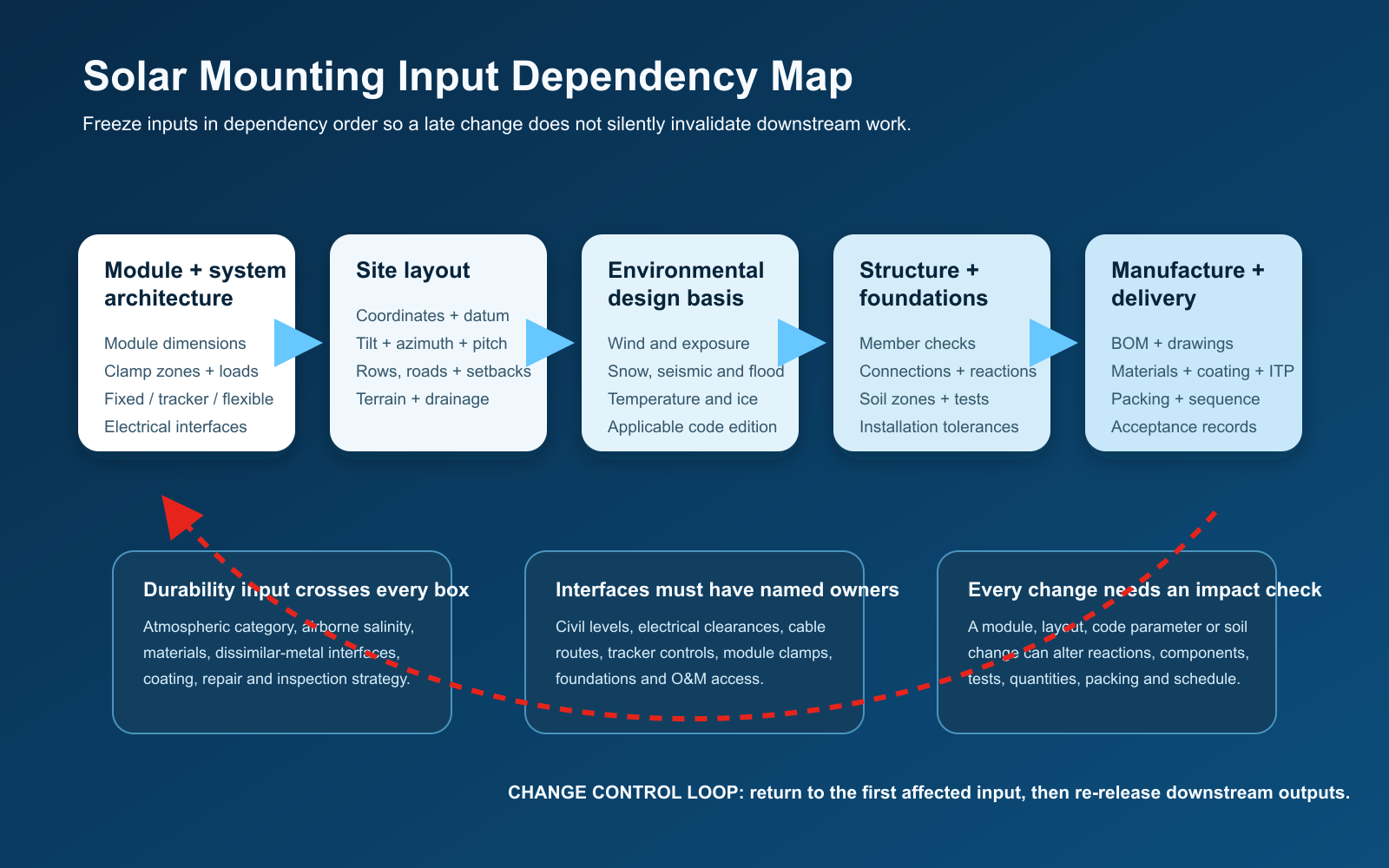
Solar mounting inputs are linked. A late module substitution can alter clamp positions, rail span, table geometry, dead load, cable routing, packing density and quantities. A row-pitch or tilt change can affect wind exposure, shading, steel geometry, foundation reactions and setting out. New survey or ground information can split one foundation solution into several site zones.
Use one change notice that identifies the old and new input, reason, affected zones, originating owner, required date and first downstream output that may be invalid. Structural, foundation, manufacturing, logistics and document-control owners should then record whether calculations, drawings, BOM, tests, packing or schedule require re-release.
- Return to the first affected input. Do not begin with the drawing where the change was noticed.
- Freeze the revised baseline. Record source, revision, approver, effective zone and status.
- Recheck every downstream interface. Include quantity, test and delivery effects, not only member strength.
- Release or reject explicitly. Supersede the old output and prevent mixed-revision manufacture or installation.
Red flags that keep the package provisional
- The request says “standard panel” but does not name a module model, dimensions or approved attachment data.
- The drawing has no coordinate system, datum, revision, zone naming or reconciliation with the survey.
- Wind, snow or seismic conditions are described only by a country, city or adjective.
- The code edition, national parameters, load combinations or responsibility for design actions are missing.
- One foundation assumption is applied across the site without linking it to geotechnical coverage and structural reactions.
- The durability requirement is only “galvanized” and does not state exposure, design-life basis, material interfaces or inspection evidence.
- The supplier is asked for a final BOM while the module, tilt, row pitch, table length or site quantity is still changing.
- Scope boundaries omit clamps, fasteners, posts, foundations, grounding interfaces, tools, spares, packing or handover records.
- A tracker quotation omits stow states, drive and control interfaces, power-loss behavior or responsibility for site-specific wind actions.
- The programme assumes production starts before drawing approval and all technical queries close.
What to send East Baoyu for an engineering review
For an efficient first review, send the best controlled version of each item below. Missing information does not need to be hidden; identify it as preliminary, state the owner and due date, and clarify which decision you want the review to support.
- Project name, country, coordinates, authority or applicable code basis, units and target review gate.
- Selected module datasheet and installation manual, quantity, orientation and permitted attachment information.
- Fixed, tracking or flexible mounting concept; tilt, azimuth, row pitch, table size and preliminary layout.
- Survey, contours, levels, access, drainage, exclusion zones, utilities and known civil interfaces.
- Issued wind, snow, seismic, temperature, flood or other environmental parameters and combinations.
- Geotechnical information, groundwater, obstructions, foundation zones, installation constraints and test expectations.
- Durability environment, design-life basis, material or coating requirements and inspection documentation.
- Supply boundary, required calculations and drawings, QA records, quantity by zone, delivery location and programme.
East Baoyu can review the available information against its solar mounting supply routes, identify missing or conflicting inputs, and define the proposed quotation and documentation basis. That review does not replace the project structural, geotechnical, civil or electrical designer, and no project-specific capacity or suitability should be inferred until the responsible parties approve the governing inputs.
Questions? Chat with Mike Ice on WhatsApp
Fast reply on capacity, price, configuration and running video.
Chat Now
Request a controlled solar mounting review
Send the module, layout, location, environmental basis, ground information, durability requirement, quantity and programme. East Baoyu will identify usable inputs, open items and the appropriate supply-review route.
Frequently asked questions
Can a mounting supplier quote before the topographic or geotechnical work is final?
Yes, if the request clearly states that the output is a screening or preliminary quotation. Define assumptions by zone, identify who will confirm them and require the offer to show what changes could affect price, foundation type or quantity. Do not release final calculations, fabrication or installation from that preliminary basis.
Who should define the project wind, snow and seismic inputs?
The project team should identify the responsible qualified designer and governing code route. The mounting supplier can apply issued parameters within its design scope and raise inconsistencies, but it should not silently choose a code edition, risk category, exposure, return period, national parameter or load combination from the location alone.
Is a PV module mechanical load rating the same as the mounting design load?
No. A module qualification or stated load rating belongs to a defined test and mounting configuration. The project still needs design actions, combinations, support and clamp details, factors and compatibility checks under the governing code and module instructions.
What changes when a project switches from fixed tilt to a tracker?
The architecture change affects geometry, moving envelopes, foundations, drive and control systems, stow states, power and communications, dynamic behavior, maintenance access and often the wind-design route. Reopen the input baseline instead of treating the tracker as a product substitution inside the old fixed-tilt layout.
What is the minimum information for a first engineering review?
Send the project location and intended review gate, module data, mounting concept, preliminary layout, available survey, applicable load-code basis, ground information, durability requirement, scope boundary, quantity and programme. Clearly label preliminary or missing items.
References
- IEC 62548-1:2023 — Photovoltaic arrays: design requirements
- ASCE/SEI 7-22 — Minimum Design Loads and Associated Criteria
- U.S. DOE FEMP — Technical Specifications for On-site Solar PV
- NREL — Photovoltaics Standard Work Specification
- IEC 62817 — Design qualification of solar trackers
- ISO 9223:2012 — Corrosivity of atmospheres
Research checked: 28 July 2026. Standards and local code editions must be reconfirmed for the actual project before use.
References, disclosure and change record
References and further verification
- IEC 62548-1:2023
- ASCE/SEI 7-22
- DOE FEMP Technical Specifications
- IEC 62817
- IEC 61215-2:2021
- IEC 61730-1:2023
- ISO 9223:2012
Disclosure: East Baoyu manufactures and supplies products discussed on this website. Structured drafting tools may assist research and editing, but technical claims, project inputs and release decisions require qualified review under the applicable project responsibilities.
Version 1.0: Initial publication with a five-gate release ladder, module and layout controls, environmental and geotechnical inputs, durability and interface workflow, RFQ comparison table, change-control steps and five buyer FAQs.
View the public Content Change Log · Corrections: info@baolaipipes.com