


Authorship, review and evidence boundary
- Technical review
- East Baoyu Engineering Editorial Team
- Reviewed
- 2026-07-29
- Scope
- General engineering and procurement guidance. This article is not a project-specific design, capacity statement, certificate, warranty, code interpretation or contract requirement.
Evidence basis: Official and public references identified in the article, together with original editorial diagrams. Project values and release decisions require qualified review under the applicable project responsibilities.
Read the Editorial PolicyA module substitution often arrives after rail spacing, clamp selection or tracker-table geometry has already been developed. The power class may match, but the frame, mass, approved support zones, junction-box position or cable reach may not. Treating the replacement as “equivalent” before those interfaces are checked can reopen drawings, quantities and verification assumptions.
Release a module to mounting design only when the exact manufacturer, model and document revisions are controlled together with geometry and tolerances, mass, frame and attachment instructions, mechanical-rating context, rear-side clearances, cables, connectors and bonding requirements. A datasheet is one source; it is not the release record. The practical next step is to build a Module Interface Release Card before design starts or any substitute is accepted.
1. The module change that reopens mounting design
The module is not simply a rectangular payload. It is the supported element, the clamped or bolted interface, an electrical component and—under some certification routes—part of a defined module-and-racking combination. A change can therefore affect more than the table footprint. It may move the permitted support line, change local frame behaviour, alter dead load and handling, obstruct a rail with the junction box, shorten cable reach, or invalidate a previously assumed bonding or listing path.
Start with the decision being released. Concept screening may tolerate declared provisional dimensions. Quotation needs a named module basis and change assumptions. Detailed design requires the current approved documents and project actions. Fabrication requires closed interfaces and revision alignment. Installation needs the approved manual, drawings and field checks. If the project cannot state which gate it is at, it cannot state whether its module information is sufficient.
| Release gate | Module information needed | Typical hold trigger |
|---|---|---|
| Concept / layout | Named module envelope, orientation, approximate mass and declared assumptions. | Module family is unidentified or alternative envelope is undefined. |
| Quotation | Exact candidate model, current datasheet and provisional interface basis. | Price assumes one module while layout or quantities assume another. |
| Detailed design | Controlled datasheet, installation manual, drawing, actions and applicable evidence. | Clamp zone, frame profile, support condition or rating context is unresolved. |
| Fabrication release | Closed interface register linked to approved calculations and drawings. | A later module revision or substitute has not completed impact review. |
| Installation | Approved instructions, hardware, torque/inspection basis and traceable module identity. | Site team cannot match delivered labels and documents to released drawings. |
2. Build the four-document module interface pack
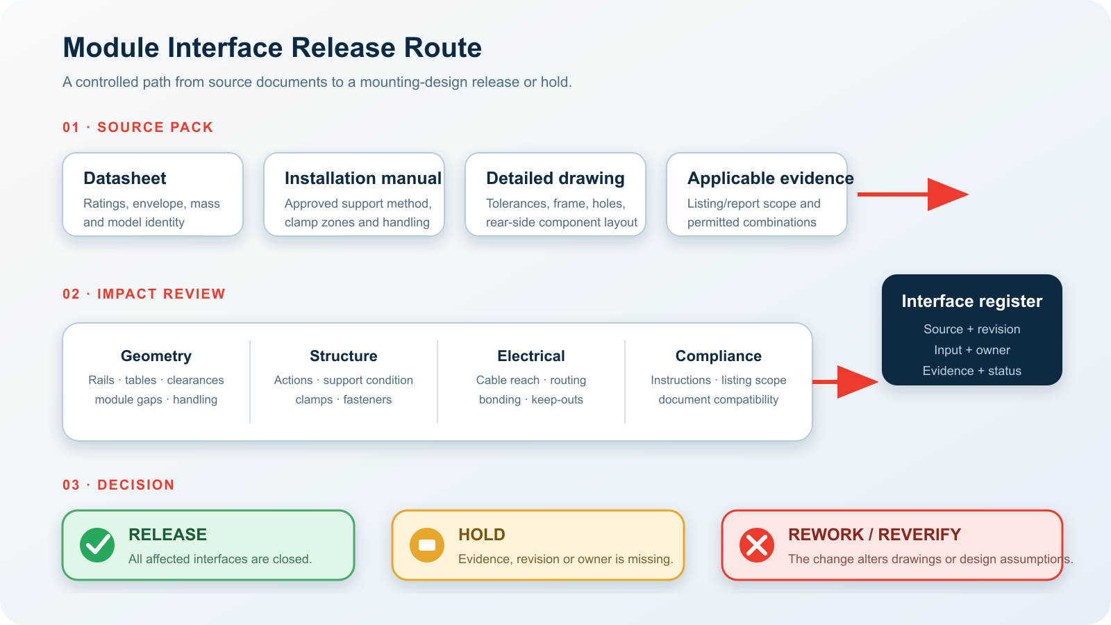
Do not ask one document to answer every question. The commercial datasheet usually gives the model identity, headline dimensions, mass, electrical data and selected ratings. The installation manual defines permitted handling and attachment arrangements. A detailed or dimensional drawing closes tolerances, frame profile, hole locations and rear-side geometry. Applicable certification, listing or assessment evidence defines what was evaluated and under which combinations or installation conditions.
Record the document number, revision or issue date, source link, received date, owner and approval state. A downloaded PDF without revision control is a reference copy, not an engineering baseline. Where the module manufacturer supplies several manuals by market, frame option or product family, confirm that the selected manual actually covers the exact delivered construction.
| Document | Extract | Do not assume |
|---|---|---|
| Datasheet | Exact model; length, width and thickness; mass; connector/cable data; stated mechanical ratings. | Every installation detail or tolerance is shown. |
| Installation manual | Permitted mounting methods, clamp zones or holes, orientation, handling, hardware and restrictions. | A family manual covers every frame or regional variant. |
| Detailed drawing | Frame cross-section, tolerances, hole coordinates, junction box, leads, connectors and keep-outs. | Nominal catalogue dimensions are adequate for released steel geometry. |
| Applicable evidence | Certificate/report identity, evaluated scope, model construction, combination and installation limitations. | A logo or “compliant” statement proves the intended module/racking use. |
Resolve document conflicts before they reach drawings
Conflicts inside the source pack are engineering inputs. The datasheet may show one nominal thickness while the dimensional drawing adds a tolerance; a family manual may describe several clamp arrangements without identifying the selected frame; or a certificate annex may list a construction code that is absent from the purchase description. Do not silently choose the value that best fits the current layout. Record the conflict, identify which released deliverables would be affected, and obtain a traceable clarification from the responsible manufacturer or document owner.
Set a project document hierarchy before the review starts. The contract and adopted project basis may define which approved document governs, but that hierarchy does not make a physical conflict disappear. If a later manufacturer drawing changes a frame or support requirement, the team must assess the change even when an earlier commercial datasheet remains contractually referenced. Keep both the superseded and current records so the decision can be audited.
Also distinguish “not shown” from “not applicable.” A missing centre of gravity, bonding point or rear-side keep-out should enter the card as an open query when it could affect the selected system. Marking it N/A requires a reason, an owner and confirmation that the current mounting architecture does not use that information.
3. Extract the geometry that controls rails, clamps and table layout
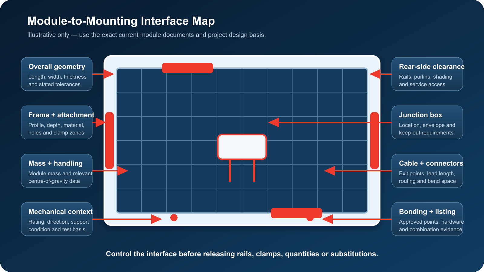
Begin with the exact overall length, width and thickness, but keep the stated tolerances beside the nominal values. Tolerances accumulate across module gaps, table width, rail overhangs and tracker rows. Mass affects dead load, manual handling and installation planning; centre-of-gravity data may also matter for unusual or moving assemblies when available. None of these values should be copied from a similar power class or marketing family.
Next resolve the frame and attachment. Record frame material, depth and cross-section; approved clamp zones and orientation; mounting-hole size, shape and coordinates; prohibited regions; required engagement; approved clamp or fastener contact; and any manufacturer limitations. A frame depth does not reveal the internal profile, and an outline drawing does not prove that any point along the long edge is clampable. The current manufacturer instructions control.
| Controlled input | Mounting decision affected | Release evidence |
|---|---|---|
| Length, width, thickness and tolerances | Table size, rail length, gaps, row geometry, overhang and transport/handling. | Current dimensional drawing cross-checked to datasheet. |
| Mass and relevant centre of gravity | Dead load, actuator/torque-tube demand where applicable and handling plan. | Manufacturer document; project calculation if the effect is material. |
| Frame profile and depth | Clamp selection, seating, edge distance, rail clearance and local interface. | Frame section or controlled detailed drawing. |
| Clamp zones / mounting holes | Support line, clamp count/position, bolt pattern and module orientation. | Exact installation manual plus applicable calculation/listing check. |
| Module gap and thermal/installation allowance | Table width, expansion accommodation and field fit-up. | Approved module and mounting instructions. |
4. Read mechanical ratings in their test and support context
A mechanical-load entry on a module datasheet is not automatically the design pressure for the project or the allowable reaction for a chosen clamp layout. Module qualification standards such as the IEC 61215 series use defined test procedures and support conditions to evaluate module designs. Project environmental actions and load combinations come from the adopted design basis—for example, ASCE/SEI 7 where adopted—and must be translated through the selected mounting architecture, tributary areas, pressure zones, load directions and safety format by qualified designers.
The comparison therefore needs both sides. On the module side: rating direction, test or design wording, support method, clamp or hole configuration, permitted zones and any stated reduction or limitation. On the project side: design actions, pressure distribution, load combinations, dynamic or operational conditions, deflection/clearance criteria and the reactions created by the racking system. If those bases are not comparable, the interface remains on hold.
This boundary is especially important for trackers and flexible systems, where operating position, stow strategy, torsional response, span, pretension or dynamic behaviour can alter how module loads enter the structure. The separate East Baoyu guides on tracker wind and flexible mounting cover those system questions; the module interface card records the inputs they require without replacing their calculations.
5. Close the rear-side, cable and bonding interfaces
Rear-side geometry can be the hidden reason a nominally identical module does not fit. Record the junction-box envelope and position, cable exit direction, connector type and location, lead length, permitted bend and support route, rear labels or service zones, and any bifacial rear-clearance or shading constraints issued for the project. Check these against rails, purlins, torque tubes, clamps, fasteners, cable clips and maintenance access.
IEC 62548-1 places array wiring, protection, switching and earthing within the PV array design context, so these are coordinated interfaces even when the steel engineer is not designing the electrical system. A mechanically convenient rail line may obstruct the junction box or create a cable route that the electrical design cannot accept. The resolution belongs in coordinated drawings and responsibility matrices, not in an informal site workaround.
| Rear/electrical input | Check against | Close-out owner/evidence |
|---|---|---|
| Junction-box envelope and keep-out | Rail/purlin position, fasteners, access and thermal/service clearance. | Module drawing + mounting GA; mechanical/electrical coordination. |
| Cable exit and lead length | String route, row transitions, movement, clips and connector reach. | Module document + cable-management drawing. |
| Connector identity | Approved mating components, project electrical specification and procurement. | Electrical designer/vendor confirmation; delivered-material control. |
| Bonding/grounding point and hardware | Frame finish, clamp/washer path, rail continuity and inspection. | Applicable instructions and listing/certification evidence. |
| Bifacial rear-side requirements | Rail shading, torque tube/purlin position, clearance and energy-model assumptions. | Project energy/layout basis plus module/system documentation. |
6. Run the module-to-mounting impact review
Use the review for the original design baseline and repeat it for every proposed substitute, revised drawing or frame construction. Do not limit the review to dimensional fit. A disciplined sequence makes the effect visible to engineering, procurement and installation:
Identify the baseline. Record exact manufacturer, model, construction option and all source-document revisions.
List every changed or unknown field. Include “not stated” and conflicts between documents; absence is an input condition, not permission to assume.
Map the affected deliverables. Check layout, calculations, rail/purlin schedules, clamps, fasteners, cable management, bonding, BOM, packing and installation instructions.
Assign an owner and evidence. Separate module-manufacturer confirmation, mounting-system verification, electrical review and project approval.
Decide release, hold or rework. Release only after every material interface is closed at the required gate and linked documents use the same baseline.
Notify downstream teams. Update procurement, fabrication, logistics, site QA and as-built records; do not close the change only inside the engineering folder.
Use a redline comparison for every substitute
A substitution review should compare the proposed module against the released baseline field by field, not against a memory of the original model. Use a redline table that shows old value, new value, source and revision, difference, affected deliverable, required action and closure evidence. Include unchanged fields as well as changed fields: an explicit match is more useful than a blank cell whose meaning is unknown.
Classify each difference by effect. A geometry change may require a layout and BOM update; a support-zone change may reopen module and racking verification; a rear-side change may affect cable management; a frame or construction change may require a new listing/certification check; and a documentation-only revision may still need confirmation that no technical interface changed. Where the impact cannot be determined from the supplied evidence, the correct status is hold—not “no impact.”
Close the redline only after downstream documents are aligned. The approved module model and revision should match calculations, general arrangements, shop drawings, clamp or fastener schedules, procurement records, packing/receiving checks and installation instructions. This final alignment is what prevents an engineering approval from being lost between purchasing and the site.
7. Release, hold or rework: the Module Interface Release Card
The release card is a compact control device, not another uncontrolled checklist. Each row must point to the source and revision, state the controlled input, show which mounting decision it affects, identify the evidence or owner that closes it, and carry a status. Add a change trigger so the row is automatically reopened when a later module revision, substitute or system change touches it.
| Source / revision | Controlled input | Decision affected | Evidence / owner | Status |
|---|---|---|---|---|
| Datasheet [ID / rev] | Exact model, envelope, tolerance, mass | Layout, rail/table geometry, handling | Controlled drawing / design lead | Open / closed |
| Manual [ID / rev] | Clamp zones or mounting holes | Support line, clamp/fastener detail | Interface check / structural lead | Open / closed |
| Drawing [ID / rev] | Frame profile, junction box, leads | Clamp fit, rear clearance, routing | GA overlay / mech-electrical leads | Open / closed |
| Report/listing [ID] | Evaluated model/system combination | Bonding, retention, fire/listing route | Applicable evidence / compliance owner | Open / N/A / closed |
| Project basis [rev] | Actions, combinations, criteria | Module and mounting verification | Calculation / responsible engineer | Open / closed |
Use “N/A” only with a stated reason and approving owner. Use “closed” only when the evidence is stored and linked. A meeting note that says “same as previous” is not a substitution comparison, and an email that confirms only overall dimensions does not close the frame, load, cable or certification interfaces.
8. What procurement should require before accepting a substitute
Procurement can prevent late redesign by making interface evidence part of the substitution package. The supplier should not be asked only for price, wattage and delivery. Require the exact candidate model and construction; current datasheet, installation manual and detailed drawing; a marked comparison against the released baseline; confirmation of frame, clamp/hole and rear-side changes; applicable certification/listing evidence; and the date by which project engineering must approve or reject the change.
Reject unnamed “or equivalent” offers when the mounting interface has not been compared.
Do not accept a family-level manual without confirmation that it covers the offered construction.
Keep commercial and engineering status separate. A favourable price is not technical approval.
Protect fabrication and shipment dates. Define the latest substitution gate and the consequences of later changes.
Match delivery to released documents. Check module labels, frame option and supplied manuals during receiving.

9. What to send East Baoyu for an engineering review
East Baoyu publicly presents fixed, tracking and flexible solar mounting families configured around the project module, layout, loads, terrain, corrosion exposure, design life and installation method. For a useful first review, send the exact module pack and enough project context to identify the interface questions—not only the datasheet.
| Send | Minimum content |
|---|---|
| Module identity | Manufacturer, exact model, construction/frame option and proposed alternatives. |
| Controlled documents | Datasheet, installation manual, detailed drawing and applicable evidence with revision/date. |
| Layout basis | Orientation, table/row arrangement, gaps, rail/purlin concept and selected mounting family. |
| Project actions | Issued wind, snow, seismic and other relevant actions with code/design-basis references. |
| Interfaces | Clamp/hole preference, rear clearance, cable/bonding route, access and installation constraints. |
| Change status | Original baseline, proposed substitution, affected drawings/BOM and required decision date. |
East Baoyu can review the product, mounting and manufacturing interfaces within the agreed scope. Final project design, code compliance, module approval, electrical design, certification/listing interpretation and authority acceptance remain with the responsible project professionals and applicable parties.
Request a controlled module-interface review
Send the exact module model and revision, installation manual, dimensional drawing, planned mounting type, layout, project actions and substitution deadline. The review can then identify missing inputs, affected mounting decisions and the proposed engineering route.

Questions? Chat with Mike Ice on WhatsApp for a fast reply on capacity, price, configuration and running video.
Open WhatsApp: +86 130 1228 3281
| Contact | Official detail |
|---|---|
| info@eastbaoyu.com | |
| Phone | +86-22-28352066 |
| +86-130-1228-3281 | |
| Website | https://eastbaoyu.com/solar-mounting/ |
Frequently asked questions
Is a PV module datasheet enough for solar mounting design?
Usually not. It is an important source for model identity, envelope, mass, electrical data and selected ratings, but the current installation manual, detailed drawing, project actions and any applicable listing or certification evidence are also needed to release the interface.
Can a higher module mechanical-load rating justify fewer clamps?
Not by itself. The rating must be read with its test/support conditions and compared with project actions and the proposed racking reactions. Clamp count, position and system verification remain project- and product-specific.
What if the replacement module has the same wattage and overall dimensions?
Those two matches do not prove equivalence. Compare tolerances, mass, frame profile, clamp zones or holes, rear-side components, cables/connectors, bonding and applicable certification/listing scope.
Are clamp zones the same for every module in one product series?
Do not assume so. Confirm that the current installation manual and drawing cover the exact model and delivered construction. A series can contain different sizes, frames or regional instructions.
Which electrical details affect a mechanical mounting system?
Junction-box position, cable exit, lead length, connector reach, cable support, bonding points and rear-side keep-outs can affect rail/purlin placement, fasteners, clearances and coordinated installation drawings.
Who approves a module substitution?
The project’s defined change process should assign the module supplier, mounting-system designer, structural and electrical designers, procurement, compliance parties and final approving authority. East Baoyu can review agreed mounting/manufacturing interfaces but does not replace project approval.
Related East Baoyu engineering resources
Solar Mounting Systems — product family and engineering inquiry
Engineering Articles — East Baoyu knowledge base
Solar Mounting Design Inputs: A Controlled Checklist for EPC and Procurement Teams
Solar Tracker Wind Load and Stow Strategy
Fixed versus Tracking PV Mounting System Selection
References and scope notes
Sources were checked on 28 July 2026. Standard scopes are paraphrased; no proprietary standard text, test table or manufacturer instruction is reproduced. Always use the project’s adopted documents and the current official edition required by the contract or authority.
IEC 62548-1:2023 — Photovoltaic arrays — Design requirements
IEC 61215-2:2021 — PV module design qualification — Test procedures
IEC 61215-1-1:2021 — Crystalline-silicon PV module qualification requirements
IEC 61730-1:2023 — PV module safety qualification — Construction requirements
IEC TS 62915:2023 — PV module modification and retesting
UL — PV Mounting Systems Certification / UL 2703
UL Question Corner — PV mounting-system certification parameters
ASCE/SEI 7-22 — Minimum Design Loads and Associated Criteria
U.S. DOE — Solar Photovoltaic System Design Basics
U.S. DOE FEMP — Install and Commission a Photovoltaic System
NREL — Observations of PV Systems Post-Hurricane
U.S. DOE — PV System Owner’s Guide to Weather Vulnerabilities
References, disclosure and change record
References and further verification
- https://wa.me/8613012283281
- https://wa.me/8613012283281?text=Hello%20East%20Baoyu%2C%20I%20would%20like%20to%20discuss%20a%20project.
- https://eastbaoyu.com/solar-mounting/
- https://eastbaoyu.com/articles/
- https://eastbaoyu.com/solar-mounting-design-input-checklist-epc-procurement/
- https://eastbaoyu.com/solar-tracker-wind-load-and-stow-strategy/
- https://eastbaoyu.com/fixed-versus-tracking-pv-energy-comparison/
- https://webstore.iec.ch/en/publication/64171
- https://webstore.iec.ch/en/publication/61350
- https://webstore.iec.ch/en/publication/61346
- https://webstore.iec.ch/en/publication/59803
- https://webstore.iec.ch/en/publication/66172
- https://www.ul.com/services/pv-mounting-systems-certification
- https://code-authorities.ul.com/wp-content/uploads/sites/46/2022/09/Sept-Oct-2022-UL-Question-Corner_FINAL.pdf
- https://www.asce.org/publications-and-news/codes-and-standards/asce-sei-7-22
- https://www.energy.gov/cmei/systems/solar-photovoltaic-system-design-basics
- https://www.energy.gov/cmei/femp/life-cycle-photovoltaic-systems-install-and-commission-photovoltaic-system
- https://www.energy.gov/sites/default/files/2021-09/pv-system-owners-guide-to-weather-vulnerabilities.pdf
Disclosure: East Baoyu manufactures and supplies products discussed on this website. Structured drafting tools may assist research and editing, but technical claims, project inputs and release decisions require qualified review under the applicable project responsibilities.
Version 1.0: Initial scheduled publication in the East Baoyu engineering knowledge-base batch.
View the public Content Change Log · Corrections: info@baolaipipes.com