

Authorship, review and evidence boundary
- Technical review
- East Baoyu Engineering Editorial Team
- Reviewed
- 2026-07-29
- Scope
- General engineering and procurement guidance. This article is not a project-specific design, capacity statement, certificate, warranty, code interpretation or contract requirement.
Evidence basis: Official and public references identified in the article, together with original editorial diagrams. Project values and release decisions require qualified review under the applicable project responsibilities.
Read the Editorial PolicyA borehole log can be complete and still be insufficient to specify a ground screw. It may describe the soil at one coordinate yet omit the site datum, seasonal groundwater, uncontrolled fill, buried obstructions, the supported structure’s load reactions or any plan for checking what happens during installation. The log is valid evidence; it is not automatically a release basis.
The useful question is therefore not “Do we have a geotechnical report?” It is “Does the available geotechnical data answer the decision we are about to make?” Screening a foundation concept needs less confidence than releasing final geometry or accepting production installation. This guide shows how EPC, engineering and procurement teams can scale the evidence to the decision without confusing a catalogue choice, a penetration test or a final torque value with project-specific foundation proof.
1. Start with the decision, not the test method
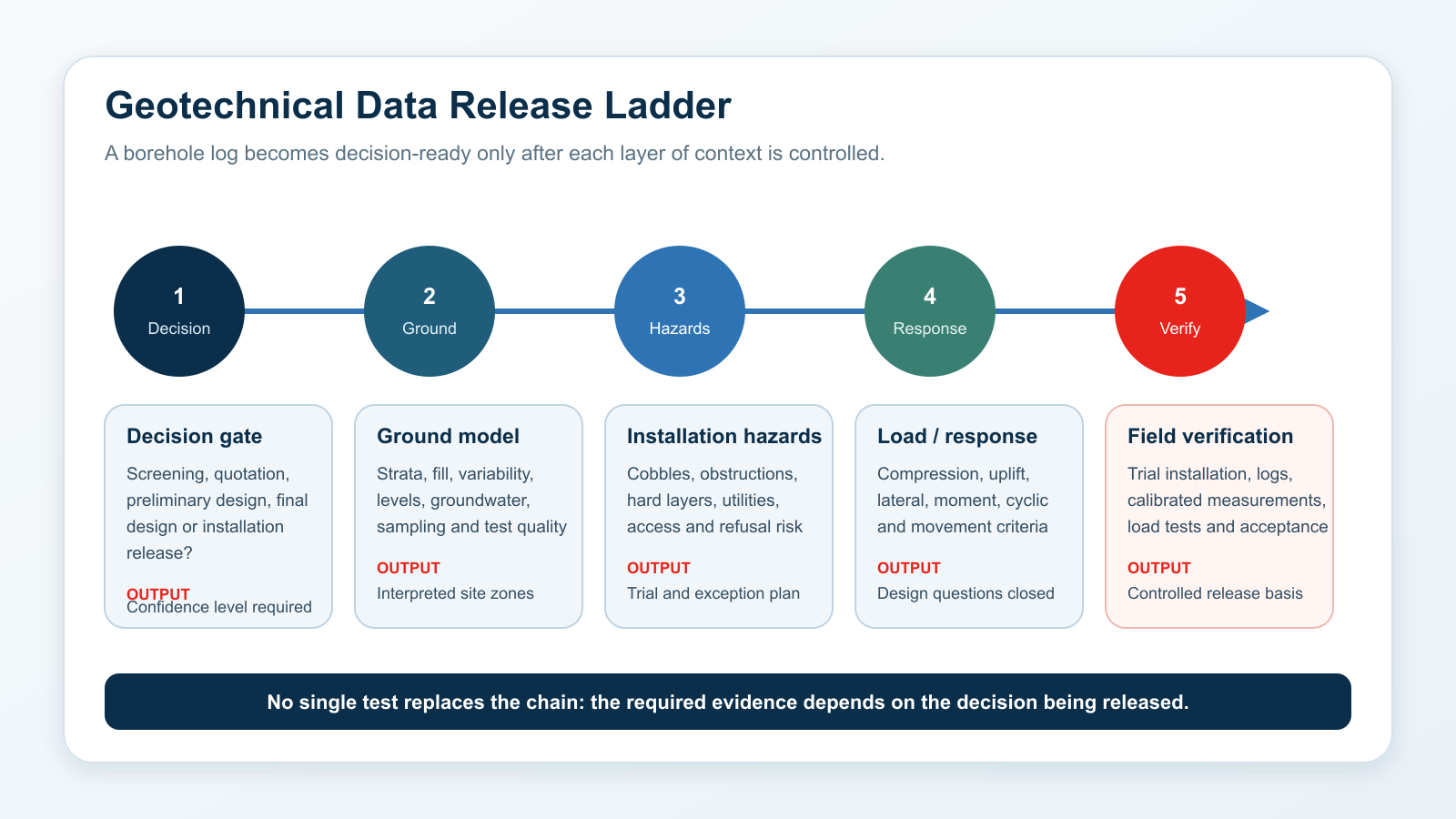
Data sufficiency changes with the release gate. A tender team may compare feasible foundation families using a preliminary ground model and declared assumptions. A designer needs project reactions, serviceability criteria and interpreted parameters for each geotechnical zone. An installer needs obstruction, access, tolerance and refusal rules. An acceptance team needs installation and test records that can be traced to locations and approved criteria. The same report can be adequate for one gate and inadequate for the next.
| Decision gate | What the data must support | Typical unresolved item that blocks release |
|---|---|---|
| Concept screening | Credible foundation family and major feasibility risks. | Unknown fill depth, rock head, obstruction prevalence or groundwater regime. |
| Quotation / tender | Defined assumptions, provisional zones, quantities, access and trial scope. | No coordinate-based investigation plan or no distinction between factual logs and interpretation. |
| Preliminary design | Load path, serviceability questions and testable ground-screw concept. | Actions, movement limits or connection fixity are not issued. |
| Final design / procurement | Released geometry, durability basis, tolerances and verification requirements. | Field trial and acceptance route is absent or dependent data remain preliminary. |
| Installation / acceptance | Location-specific records, exceptions, tests and dispositions. | No traceable link between installed element, zone, method, measurement and result. |
2. Build a project-wide ground model, not a folder of logs
A ground model connects observations across the site and records the uncertainty between them. It should show where each borehole, cone penetration test (CPT or CPTu), test pit, sample and groundwater observation was taken; the coordinate system and elevation datum; the interpreted strata and boundaries; and the evidence quality behind each zone. FHWA guidance treats planning, investigation, laboratory and in-situ testing, interpretation and reporting as connected activities. That connection is what turns raw logs into usable project information.
Keep factual and interpreted information visibly separate. A recovered sample, an SPT blow count, cone resistance, an observed water level and a logged obstruction are observations. A continuous layer boundary, characteristic parameter, expected rock surface or probability of refusal is an interpretation. Both are valuable, but only if the specification makes clear which is which and who approved the interpretation.
| Data group | Minimum control | Ground-screw decision affected |
|---|---|---|
| Location and level | Coordinates, ground level, datum, investigation depth and termination reason. | Whether evidence is relevant to the actual foundation zone and toe/elevation concept. |
| Soil and rock profile | Descriptions, boundaries, fill status, sample recovery and test references. | Installability, shaft/helix interaction, lateral response and trial depth range. |
| Variability | Zone boundaries, abrupt changes, data gaps and confidence statement. | Number and placement of trials, alternative geometry and exception rules. |
| Groundwater | Observed level, date, datum, monitoring period and anticipated variation where relevant. | Installation conditions, durability questions, effective stress and test interpretation. |
| Obstructions / site history | Made ground, debris, prior foundations, cobbles, boulders, utilities and remediation. | Refusal risk, predrilling/relocation questions, tooling, access and contingency. |
| Laboratory / in-situ quality | Method, equipment, calibration or energy data where applicable, sample condition and limitations. | Whether correlations and design parameters are defensible for the intended gate. |
3. Map installation hazards explicitly
A conventional geotechnical summary may emphasize strength and settlement, while installation risk depends on different details. Coarse fill, cobbles, boulders, slag, buried concrete, roots, cemented layers, shallow rock, very soft pockets and underground services can interrupt penetration, damage a component, deflect alignment or produce a misleading resistance peak. A useful package flags these hazards by location and explains how they were detected—or why uncertainty remains.
Do not convert an SPT refusal or a single high resistance reading directly into a ground-screw refusal criterion. The tool, sampler or cone has a different geometry and penetration process from the proposed foundation. Instead, define the hazard, locate the evidence, state its limits and decide what a trial installation must observe. The installation method statement should then include a controlled response: continue, change tooling, predrill if permitted, relocate, change the concept, or stop for engineering disposition.
Record the site history — previous structures, demolition, filling, grading, mining, buried services and known remediation.
Describe the obstruction evidence — actual recovery or observation, geophysics, probing, refusal notes and the depth/elevation at which it occurred.
Tie hazards to zones — avoid one generic statement such as “possible cobbles” for a large and variable site.
Define the exception route — who stops work, what is recorded, who decides and which alternative is permitted.
4. Zone the site by uncertainty, not by average values
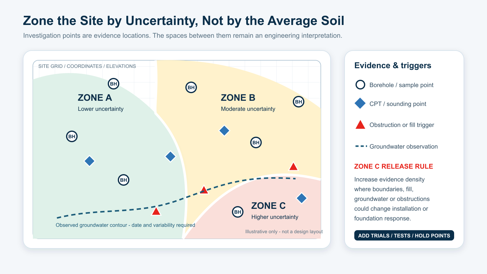
Investigation points do not create a continuous proof surface. Between them, the ground model is an engineering interpretation informed by geology, geomorphology, site history and the observed pattern. Large solar or light-structure sites are especially vulnerable to false averaging: a mean SPT value or one representative soil profile can hide a drainage channel, a filled depression, a cut-to-fill boundary or a shallow-rock transition that controls installation.
Create zones that are useful for decisions. A lower-uncertainty zone may have consistent logs and a simple geological setting. A moderate zone may need additional trial points. A higher-uncertainty zone may require closer investigation, alternative products or an explicit hold point before production. Zone boundaries should be revision-controlled and transferred to the layout, trial plan and as-built register.
5. Match each investigation method to the question
No method is automatically “enough.” ISO 14688-1 provides a current framework for identifying and describing soils for engineering purposes; it does not determine foundation capacity. ASTM D1586/D1586M defines the SPT and split-barrel sampling process. SPT can provide a disturbed sample for identification and a penetration-resistance record, but the procedure, hammer energy, interval, material size and sample disturbance affect what can be inferred.
ASTM D5778 covers electronic friction-cone and piezocone testing. CPT/CPTu can provide a detailed continuous resistance profile and support interpretation of stratigraphy and homogeneity at suitable sites, but it recovers no soil sample. Parallel borings, test pits or other methods may be needed to identify material, investigate fill or correlate interpretations. Test pits can reveal shallow fill and obstructions directly; geophysics can extend coverage but usually requires site-specific interpretation and confirmation.
6. Convert structural actions into geotechnical questions
The ground model cannot be judged in isolation from the supported asset. Issue compression, uplift, lateral force and moment for the relevant load combinations, plus cyclic or fatigue-related actions where they matter. Also issue serviceability limits: settlement, uplift movement, horizontal displacement, rotation, differential movement and connection tolerance. The geotechnical team needs these to decide which layers and parameters control; the structural team needs the ground response to check shaft, head and supported-frame behavior.
Near-surface ground often has a strong influence on lateral response and rotation, while deeper strata may control axial behavior. Projection above ground, scour or future grading, group spacing, head fixity and installation tolerance can change the response. Do not ask the geotechnical report for a single “allowable capacity” without defining load direction, movement criterion, design format, foundation geometry and verification basis.
7. Use trial installation and load testing as verification
Investigation reduces uncertainty; field verification checks whether the selected system behaves as assumed. A trial record should identify location, ground level, product and revision, equipment and tooling, installation orientation, penetration history, depth/elevation, rotations or advance, measured torque where used, interruptions, refusal or damage, and the disposition. Measurements need stated units, method and calibration status. The record is valuable only when it can be traced to a zone and an approved decision.
Installation torque is not capacity by itself. A correlation may be useful only for a defined product geometry, installation method, ground profile and load direction supported by project evidence. ICC-ES AC358, for example, uses controlled full-scale axial testing and reporting of installation details in its evaluation context; that acceptance criterion is not a universal project specification and does not establish that an arbitrary final torque proves compression, uplift, lateral or moment resistance.
ASTM D1143/D1143M and D3689/D3689M provide procedures for static axial compression and tension tests on deep foundation elements. They measure the response of the tested element, not every untested location. The test plan must therefore define objectives, test zones, product configuration, installation method, loading procedure, instrumentation, interpretation, acceptance and the limits of extrapolation. A qualified geotechnical or foundation engineer should approve that plan and interpret the results.
8. Assemble a minimum geotechnical data release package
The package should be a controlled set, not a chain of emails. The following sequence is compact enough for procurement but specific enough to expose missing decisions.
Define the gate. State whether the package is for screening, quotation, preliminary design, final design, trial installation or acceptance.
Issue the site basis. Provide coordinates, survey datum, layout, grading, drainage, access, services and supported-asset description.
Register the investigation. List every borehole, CPT/CPTu, test pit, sample, geophysical line and groundwater point with coordinates, levels, dates and methods.
Release the interpreted ground model. Show strata, fill, rock, groundwater, variability, installation hazards, zones, parameters and uncertainty.
Issue actions and criteria. Provide load combinations, head geometry/fixity, movement limits, design life basis and relevant project standards.
Define verification. Specify trial locations, installation records, test methods, calibration, acceptance criteria, sampling and exception handling.
Close assumptions. Name each unresolved item, its owner, due date and the decision it holds; withdraw superseded revisions.
9. Detect common data failures before procurement
| Failure mode | Why it matters | Corrective action |
|---|---|---|
| One borehole treated as the site | Local evidence is extrapolated without a geological or zoning basis. | Map evidence and uncertainty; add investigation or trial zones where change is credible. |
| Average SPT value | Layering, energy/procedure context and refusal/obstruction information disappear. | Use logs and interpreted strata; state the correlation and its limitations. |
| Groundwater shown without date or datum | The level cannot be compared with ground, toe or seasonal conditions. | Record elevation/reference, date, method and monitoring/variation basis. |
| Fill described as natural soil | Variability and buried debris risk are understated. | Separate made ground, site history and obstruction evidence. |
| Torque copied into the capacity column | Construction resistance is mistaken for foundation response. | Define and test any site-/product-specific correlation; retain load and movement evidence. |
| No exception workflow | Crews improvise after refusal, deviation or damage. | Create stop, record, review, disposition and re-verification steps before production. |
10. What to send East Baoyu for an engineering review
For a useful first review, send the current controlled files and identify what remains preliminary. East Baoyu can then map product and manufacturing questions to the project inputs without presenting a catalogue option as a final foundation design.
Site and layout — coordinates, levels, grading, access, utilities, supported asset and foundation schedule.
Geotechnical evidence — full report, factual logs, locations, samples, laboratory/in-situ data, groundwater and site-history information.
Interpretation — ground model, zones, parameters, installation hazards, uncertainty and any geotechnical recommendations.
Structural interface — reactions/load combinations, movement criteria, head connection, projection, tolerances and design responsibility.
Verification basis — trial and test objectives, methods, acceptance, installation records, calibration and exception route.
Commercial controls — quantity, required documents, programme, applicable contract/code editions and submission format.

Email: info@eastbaoyu.com | Phone: +86-22-28352066 | WhatsApp: +86 130 1228 3281
Frequently asked questions
How many boreholes are needed for a ground screw project?
There is no responsible universal number. The programme depends on site size, geology, variability, supported asset, decision stage and the consequences of uncertainty. The project geotechnical engineer should select the spacing, depth and mix of methods, then explain how conditions are interpreted between points. Trial installation and verification may be especially important where repeated foundations extend beyond the investigation locations.
Is SPT data enough to specify ground screws?
SPT data can be useful for soil identification and penetration-resistance context, but it is only one part of the package. The team still needs coordinates and levels, an interpreted ground model, fill and obstruction information, groundwater, project loads, movement criteria and a verification plan. Procedure and energy context also matter when correlations are used.
When is CPT or CPTu useful?
CPT/CPTu is useful when a continuous in-situ resistance profile can clarify stratigraphy, homogeneity or firm-layer depth at a suitable site. It does not recover a sample, so complementary borings or test pits may be needed to identify material, investigate fill and calibrate interpretation. Gravel, obstructions and very hard layers can also limit penetration.
Can installation torque prove ground screw capacity?
Not by itself. Torque is a construction response. A capacity correlation must be established for the defined product, method, ground conditions and load direction, then checked with an approved project test programme. Lateral and moment behavior, movement limits, depth, alignment and structural limits require separate consideration.
What if the site contains fill, cobbles or buried debris?
Map the evidence and uncertainty, divide the site into installation zones and plan controlled trials. The method statement should define what counts as an interruption or refusal, what is recorded, when work stops and who approves relocation, alternative tooling, permitted predrilling or a changed foundation concept. Do not hide the risk inside a general note.
Who approves the final geotechnical basis?
The authority depends on the contract and jurisdiction, but final ground-model interpretation, design parameters, verification plan and acceptance should be approved by the responsible qualified project professionals. A supplier can support product data and manufacturing interfaces; it should not replace the project geotechnical or structural engineer.
Related East Baoyu resources
Use the pages below for the adjacent decisions. They are linked deliberately so this guide does not duplicate the full design-input, selection or torque-control workflows.
Ground Screw Design Input Checklist for EPC and Procurement Teams
Ground Screw Selection from Site Investigation
Installation Torque and Ground Screw Capacity
Corrosion Design for Ground Screws, Solar Mounting and Structural Steel
References and application notes
The project contract, legally adopted codes and responsible engineers control. The sources below define current guidance or test-method scope; they do not establish East Baoyu certification, a universal investigation density or a site-independent ground screw capacity. Confirm current editions, errata and project amendments before use.
FHWA — Subsurface Investigation and Geotechnical Site Characterization resources
FHWA — GEC No. 5 Geotechnical Site Characterization listing
ISO 14688-1:2017 — Identification and description of soils
ASTM D1586/D1586M-18 — Standard Penetration Test and split-barrel sampling
ASTM D5778-20 — Electronic friction cone and piezocone testing
ASTM D1143/D1143M-20 — Static axial compressive load testing
ASTM D3689/D3689M-22 — Static axial tensile load testing
ICC-ES AC358 — Helical Pile Systems and Devices
Research checked: 28 July 2026.
Editorial image record
| Image | Rights / role | Publication boundary |
|---|---|---|
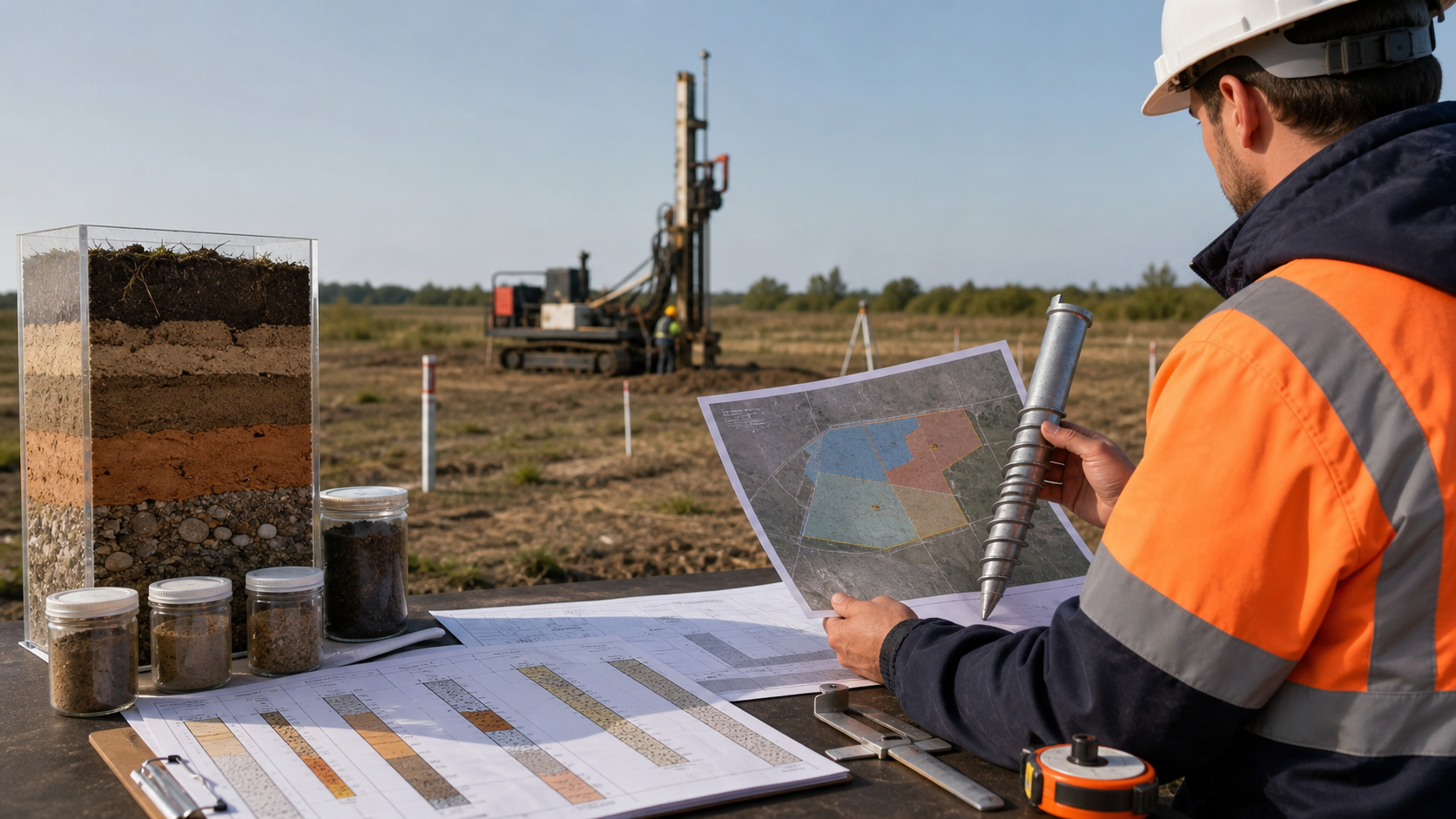
| Hero: geotechnical data for ground screws | AI-generated by OpenAI image generation for EB-ART-004. | Conceptual only; not a project, borehole log or test result. |
| Geotechnical Data Release Ladder | Original East Baoyu editorial SVG/PNG. | Explanatory workflow; not a code or acceptance specification. |
| Site Zoning and Uncertainty Matrix | Original East Baoyu editorial SVG/PNG. | Illustrative site plan; not an investigation layout. |
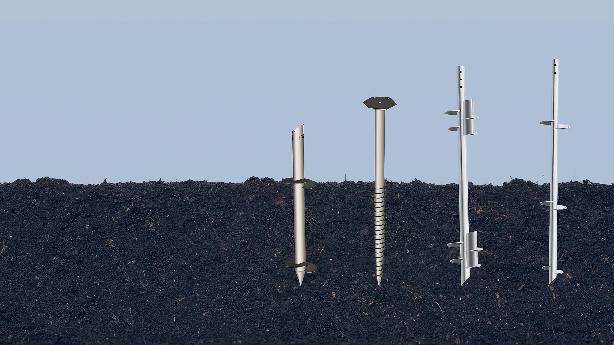
| Ground screw product-family montage | Downloaded from East Baoyu WordPress media library. | Product-family context only; no site suitability or capacity claim. |
| WhatsApp CTA | Approved East Baoyu contact graphic. | Links to the formal WhatsApp number with a generic project message. |
References, disclosure and change record
References and further verification
- https://wa.me/8613012283281
- https://eastbaoyu.com/screw-piles/
- https://eastbaoyu.com/ground-screw-design-input-checklist-epc-procurement-teams/
- https://eastbaoyu.com/ground-screw-selection-from-site-investigation/
- https://eastbaoyu.com/installation-torque-and-ground-screw-capacity/
- https://eastbaoyu.com/corrosion-design-ground-screws-solar-steel/
- https://www.fhwa.dot.gov/engineering/geotech/subsurface/
- https://www.fhwa.dot.gov/Engineering/geotech/library_sub.cfm?keyword=017&sortheader=default
- https://www.iso.org/standard/66345.html
- https://store.astm.org/d1586_d1586m-18.html
- https://store.astm.org/standards/d5778
- https://store.astm.org/d1143_d1143m-20.html
- https://store.astm.org/d3689_d3689m-22.html
- https://icc-es.org/evaluation-report-listing/ac358/
Disclosure: East Baoyu manufactures and supplies products discussed on this website. Structured drafting tools may assist research and editing, but technical claims, project inputs and release decisions require qualified review under the applicable project responsibilities.
Version 1.0: Initial scheduled publication in the East Baoyu engineering knowledge-base batch.
View the public Content Change Log · Corrections: info@baolaipipes.com