

Authorship, review and evidence boundary
- Technical review
- East Baoyu Engineering Editorial Team
- Reviewed
- 2026-08-24
- Scope
- General engineering and procurement guidance. This article is not a project-specific design, capacity statement, certificate, warranty, code interpretation or contract requirement.
Evidence basis: Official and public references identified in the article. Project values and release decisions require qualified review under the applicable project responsibilities.
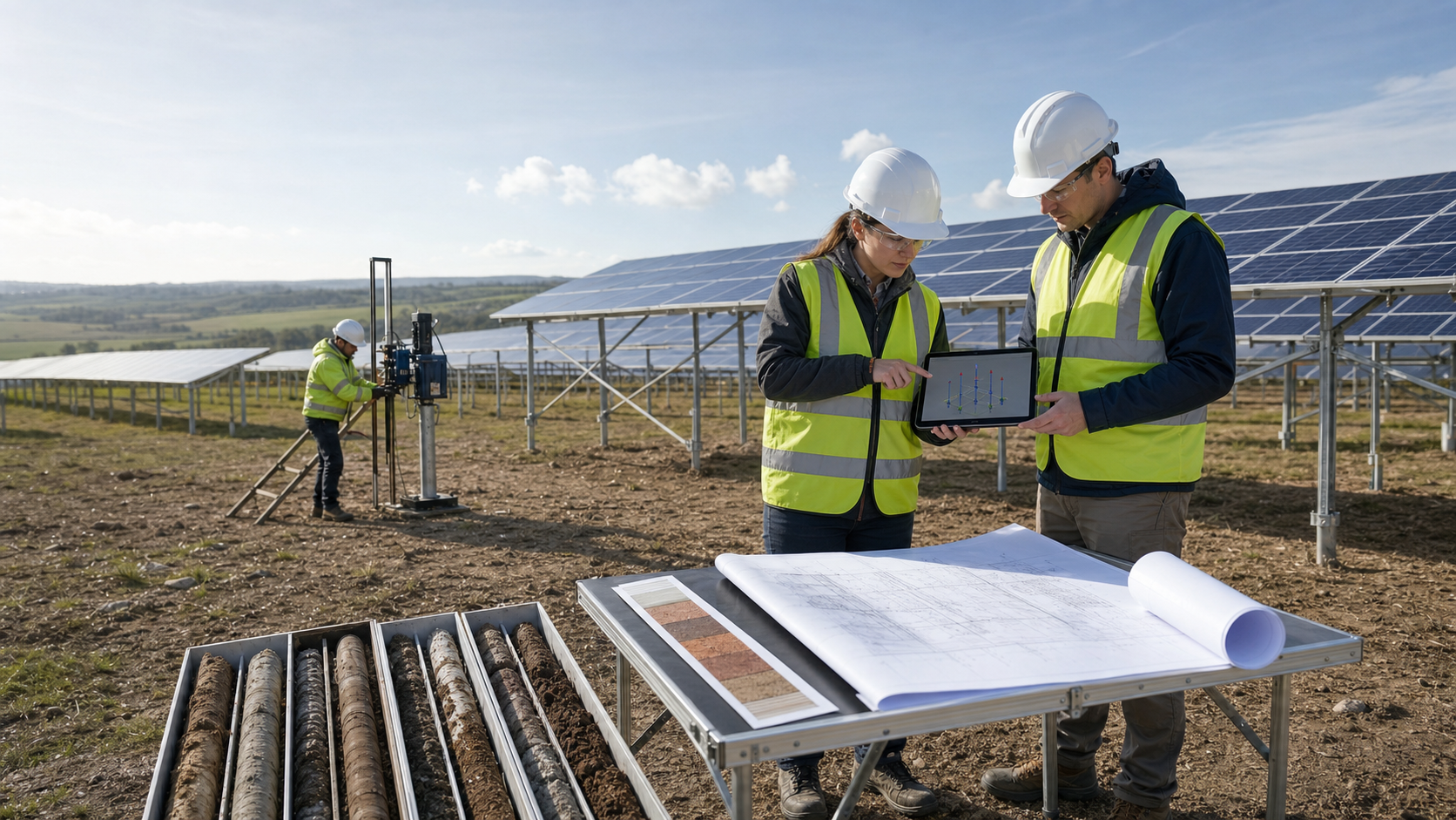
Read the Editorial PolicyThe right fixed-tilt solar mounting foundation is not selected from a soil label or a supplier catalogue. It is released for a defined site zone after the project connects ground conditions, table reactions, environmental exposure, installation response and field evidence. A route that works in one zone may be unproved in another. This guide shows how an EPC, geotechnical lead or structural interface engineer can zone the site, screen candidate routes, define test questions and control production changes. It does not size a foundation, set test loads, replace the geotechnical design or recommend one foundation type for every project.
Make the Foundation Route the Decision Object
“Use piles” is not a foundation decision. A controllable route has at least five linked parts:
- a foundation element or support concept;
- its connection to the fixed-tilt table;
- the ground and environmental conditions where it may be used;
- the installation method and acceptance controls; and
- the engineering evidence that releases it.
Treat that combination as a foundation route. Give each route and each site zone an identifier. The deliverable proposed here is a Foundation Zone Release Basis (FZRB): a revision-controlled schedule showing which route is released, conditionally released or held in every defined zone.
This boundary prevents three common category errors. First, a product datasheet is not a site-specific geotechnical design. Second, a successful test element does not automatically represent different soil, groundwater, grading or installation conditions. Third, a foundation design does not control production unless its zoning, installation and verification rules reach the field records.
The Fixed PV Bracket page owns the commercial system route. This article begins after a preliminary fixed-tilt table concept exists and ends at a zone-specific foundation release. It does not choose the tilt, table geometry, structural system or supplier.
Use three statuses:
- Released: the named route is supported for the stated zone, design basis and production controls.
- Conditional: only a bounded activity may proceed under an explicit condition, owner and expiry; the missing item cannot prejudice the final foundation decision.
- Held: design, procurement or production for that route and zone cannot proceed until the blocking evidence is resolved.
Divide the Site by Engineering Difference
A foundation zone is an area where the same ground model, foundation route, installation method and verification logic can reasonably apply. It is not simply a drawing grid or equal-size block. Zone boundaries should follow changes that can alter performance or construction response.
Begin with the geotechnical model and topographic/site-development information. Reconcile boreholes, test pits, soundings or other investigations with surface geology, fills, previous land use, groundwater observations, drainage, grading, buried utilities, access and environmental exposure. The geotechnical–structural input workflow explains how these input classes meet; the FZRB adds the spatial release decision.
| Zone-defining field | Evidence to map | Why it can change the route | Required disposition |
|---|---|---|---|
| Subsurface profile | Investigation points, strata interpretation and uncertainty | Installation response and load-transfer model may differ | Define boundary or collect more evidence |
| Groundwater and moisture | Observations, seasonal basis, drainage and inundation exposure | Construction condition, durability and ground response may change | State design condition and monitoring need |
| Fill, disturbance or prior use | Fill limits, compaction evidence, obstructions and buried features | Variability or refusal risk may not match natural ground | Separate zone and define contingency |
| Topography and earthworks | Existing/proposed grades, cuts, fills, slopes and erosion paths | Final embedment, unsupported length and surface restraint can change | Reconcile with final grading revision |
| Structural demand | Approved table family, reaction set and load-reference revision | Different table reactions or interface geometry can govern | Map each table family to its zone |
| Installation access | Equipment envelope, working platform and utility constraints | The approved installation method may not be executable | Approve alternate route before mobilization |
| Exposure and durability | Soil/water chemistry, flood/scour, frost and corrosion basis | Section loss or ground support can change over time | Define project-specific durability treatment |
This Foundation Zone Definition Table is not a substitute for a geotechnical report. It is the index that connects the report, structural reaction schedule, civil model and construction plan to one spatial decision.
Avoid both extremes. One site-wide zone can hide material differences. A separate zone around every investigation point implies precision that the ground model may not support. The geotechnical and structural engineers should define boundaries from engineering significance and state where uncertainty remains.
Screen Routes Against Constraints, Not Soil Names
Candidate routes can include directly driven steel elements, screw or helical elements, drilled or cast systems, and shallow or ballasted supports. These are route families, not interchangeable products. Do not pair them with a one-word soil description and call the selection complete.
| Candidate route family | Questions before it remains on the shortlist | Installation evidence to request | Engineering proof focus |
|---|---|---|---|
| Directly driven steel element | Can the planned section be installed through the mapped profile without unacceptable damage, deviation or refusal? | Equipment/method, trial log, penetration response, damage and alignment record | Axial/lateral response, structural integrity, durability and zone transferability |
| Screw or helical element | Can the geometry and installation method reach the intended founding condition while preserving the element and interface? | Installation procedure, rotation/advance records, obstruction and deviation rules | Project load response, installation correlation limits and production acceptance |
| Drilled or cast system | Can bore stability, spoil, groundwater, reinforcement/anchor and concrete/grout placement be controlled? | Bore/shaft record, material batch and placement evidence, as-built geometry | Ground/element interaction, construction quality and interface tolerance |
| Shallow or ballasted support | Are near-surface conditions, drainage, preparation, sliding/overturning/bearing checks and movement limits resolved? | Formation inspection, preparation, materials, level and position records | Governing limit states, differential movement and environmental exposure |
The Foundation Route Screening Matrix should record an exclusion reason as carefully as an inclusion. A route may be technically possible but incompatible with access, utility clearance, permitting, environmental conditions, schedule sequence or available quality controls. Conversely, fast installation does not prove that a route satisfies the project’s structural, geotechnical or durability requirements.
Use the ground screw selection route when a screw element remains a candidate. Use the screw piles versus concrete foundations guide for the narrower comparison between those alternatives. The FZRB sits above both: it decides where any selected route is allowed and what evidence carries that decision.
Do not lock procurement quantities while material zone boundaries, grading or test outcomes can still change the route. Preserve alternatives until the project identifies the consequence of a failed trial, an obstruction band or a changed table family.
Turn Table Reactions into Test Questions
Foundation evidence must answer the structural questions actually delivered at the table-to-foundation interface. Record the reaction source, design-code basis, load combination reference, coordinate system, application point, direction/sign convention, stiffness or movement assumptions and table family. Separate design reactions from field-test loads; their numbers and purposes are not automatically the same.
The 2026 ASCE manual chapter on foundation design for solar PV structures publicly describes geotechnical investigation, pile load testing, geotechnical/structural design, frost, scour, expansive soils, special soil topics and corrosion as foundation considerations. It also notes that fixed-tilt systems are among the PV structures covered. This supports a multi-condition proof basis, not a universal foundation detail.
Create a Test Question Register for each route-zone pair:
- Which project limit state or movement question must the evidence address?
- Which foundation element, geometry, installation method and ground condition does the result represent?
- Is the test for feasibility, design interpretation, production verification or acceptance?
- Which instrumentation, datum, loading sequence and observation record does the project procedure require?
- Who designs the reaction system, approves safety controls, interprets the result and authorizes transfer to production elements?
- What differences would prevent the result from being extrapolated across a zone?
Use the adopted project specification and current licensed standards. The official scopes of ASTM D1143/D1143M-26, ASTM D3689/D3689M-25 and ASTM D3966/D3966M-25 address static axial compression, static axial tension and static lateral loading of deep foundation elements, respectively. Their public pages also place interpretation and project-specific additions with qualified engineering roles. These references do not set the project’s required test directions, quantities, loads, duration, acceptance criteria or extrapolation rules.
One result should never be labelled simply “passed.” Record what question was answered, the interpreted basis, the zone it represents, the conditions at the time of testing and the limits on use.
Escalate Proof Before Production Is Frozen
Foundation development should move from broad uncertainty to controlled production. Each step either reduces uncertainty or exposes a need to revise the zone, route or investigation plan.
This Foundation Proof Escalation Ladder distinguishes four evidence functions:
- Site characterization supports the ground model and zone boundaries.
- Constructability trials show how the candidate element and equipment interact with mapped conditions.
- Project-specific load evidence supports the engineer’s design interpretation for the defined route and zone.
- Production verification checks whether installed work remains within the released route and its acceptance procedure.
Do not merge these functions into one generic “pull test.” A test method, test purpose and acceptance rule must align. The ground screw load test planning guide provides a separate framework for test purpose, sample logic and records when ground screws are involved.
Plan the fallback before starting trials. Define what happens after refusal, excessive deviation, element damage, unexpected groundwater, a non-representative reaction setup or an interpreted result that does not close the design question. A fallback can mean more investigation, a new zone, a changed installation method, a revised foundation route or a structural-table adjustment—subject to accountable approval.
Transfer the Released Route into Production Records
A design calculation and test report do not control thousands of production locations by themselves. The released foundation route must become field-readable instructions and traceable records.
Map the FZRB zone and route identifiers into the layout, foundation schedule, table-family register and installation work package. For each installed element or controlled lot, retain the location, route/revision, element identity, material or batch evidence as required, installation equipment/method, relevant installation observations, as-built position/elevation, deviations, nonconformities, verification tests and release status.
The ASCE 2026 Design and Construction of Solar PV Structures publicly includes construction QA/QC and commissioning in its scope. Its chapter summary calls for installation tolerances to be supplied through project drawings and manufacturer instructions, inspections/testing during construction, and a production pile testing protocol developed by the Engineer of Record. The project must obtain and apply the licensed requirements it adopts; this article does not reproduce them.
Production controls should answer five practical questions:
- How does the installer know the applicable route and current revision at a location?
- Which field observation or measurement is recorded, by whom and with what equipment status?
- Which deviation requires immediate stop, segregation or engineering review?
- How are repairs, removals, replacements and alternate foundations linked to the original location?
- Which record releases the foundation-to-racking connection and the next operation?
Do not treat installation response as a universal proxy for capacity. Correlation can be useful only when the project establishes its basis, limits, measurement quality and transfer conditions. Preserve raw field records as well as the interpreted status so that later anomalies can be traced.
Reopen the Route When Conditions Change
Foundation release is valid only for its stated ground, structural, environmental and production basis. Changes that can reopen the decision include revised table geometry or reactions, new grading/drainage, changed groundwater assumptions, an altered element or connection, different installation equipment, obstruction/refusal patterns, movement outside the approved basis, damaged coatings, revised corrosion exposure, new buried utilities or production records that no longer represent the test condition.
The U.S. Department of Energy guidance on flood damage to solar PV systems identifies standing water, scour/erosion, wet-soil support, corrosion and frost-jacking concerns for foundations. Its page focuses on smaller on-site systems and says that some lessons may also apply to utility-scale work. Use those conditions as review prompts, not as a substitute for project hydrology, geotechnical or durability design.
| Release gate | Evidence question | Release condition | Hold or reopen trigger |
|---|---|---|---|
| Zone basis | Are ground, grading, water, exposure and uncertainty mapped to a controlled revision? | Zone boundary and design conditions are approved | New data conflict with the mapped condition |
| Structural interface | Are table family, reactions, coordinates and connection assumptions current? | One traceable interface basis applies | Geometry, reaction or stiffness basis changes |
| Route feasibility | Can the element and method be installed under the mapped constraints? | Trials and method records represent the zone | Refusal, damage, deviation or access differs materially |
| Engineering proof | Do field tests and interpretation answer the zone’s defined questions? | Accountable engineer releases the bounded use | Result, setup or extrapolation remains unresolved |
| Production control | Are location, method, observations, deviations and verification traceable? | Field package can preserve the released basis | Records, equipment or acceptance route is uncontrolled |
| Change control | Are changes contained, evaluated and closed before restart? | No open change affects the route-zone pair | Affected work cannot be segregated or disposition is pending |
The Foundation Zone Release Gate should identify the approver, date, zone/route, input revisions, conditions, exclusions, production controls and supersession rule. A conditional release is unsuitable when a missing item could change foundation adequacy, test validity, installation safety or acceptance. Use a hold until the accountable reviewer can define a bounded route.
Next Step: Build the Foundation Zone Release Basis
Start the FZRB before foundation procurement is frozen. Assemble the site investigation and ground model, existing/proposed grading, groundwater and drainage basis, environmental exposure, underground constraints, table families and reactions, candidate route definitions, connection details, trial plan, test questions, interpreted results, production method, acceptance procedure and change register.
Use the Fixed PV Bracket route to confirm the preliminary mounting-system boundary. Then send a controlled input index to info@baolaipipes.com for a written scope-confirmation request. State the unresolved zones and the approvals retained by the project’s geotechnical engineer, structural Engineer of Record, civil team and authority having jurisdiction. The response should define what information is missing; it should not be treated as foundation design or approval unless the contract explicitly assigns that authority.
Related Resources
- Fixed PV Bracket — parent route for the fixed-tilt mounting-system scope.
- Combining Geotechnical and Structural Inputs for Solar Mounting — coordinate the inputs that feed the zone basis.
- Ground Screw Selection from Site Investigation — evaluate screw-element suitability without inferring it from soil names.
- Screw Piles vs Concrete Foundations — compare two narrower foundation alternatives under project conditions.
- How to Plan a Ground Screw Load Test Program — define test purpose, scope and records when ground screws remain a candidate.
References
- American Society of Civil Engineers, Foundation Design, Chapter 5 of Design and Construction of Solar PV Structures, MOP 162, 2026.
- American Society of Civil Engineers, Design and Construction of Solar PV Structures, MOP 162, 2026.
- ASTM International, ASTM D1143/D1143M-26 — Standard Test Methods for Deep Foundation Elements Under Static Axial Compressive Load.
- ASTM International, ASTM D3689/D3689M-25 — Standard Test Methods for Deep Foundation Elements Under Static Axial Tensile Load.
- ASTM International, ASTM D3966/D3966M-25 — Standard Test Methods for Deep Foundation Elements Under Static Lateral Load.
- U.S. Department of Energy, Federal Energy Management Program, Preventing and Mitigating Flood Damage to Solar Photovoltaic Systems.
References, disclosure and change record
References and further verification
- https://eastbaoyu.com/solar-mounting/fixed-pv-bracket/
- https://eastbaoyu.com/combining-geotechnical-structural-inputs-solar-mounting/
- https://eastbaoyu.com/ground-screw-selection-from-site-investigation/
- https://eastbaoyu.com/screw-piles-vs-concrete-foundations/
- https://ascelibrary.org/doi/10.1061/9780784486849.ch5
- https://store.astm.org/d1143_d1143m-26.html
- https://store.astm.org/d3689_d3689m-25.html
- https://store.astm.org/d3966_d3966m-25.html
- https://eastbaoyu.com/plan-ground-screw-load-test-program/
- https://ascelibrary.org/doi/10.1061/9780784486849
- https://www.energy.gov/cmei/femp/preventing-and-mitigating-flood-damage-solar-photovoltaic-systems
Disclosure: East Baoyu manufactures and supplies products discussed on this website. Structured drafting tools may assist research and editing, but technical claims, project inputs and release decisions require qualified review under the applicable project responsibilities.
Version 1.0: Scheduled in the East Baoyu 30-article engineering knowledge-base batch on 2026-08-25.
View the public Content Change Log · Corrections: info@baolaipipes.com