


Authorship, review and evidence boundary
- Technical review
- East Baoyu Engineering Editorial Team
- Reviewed
- 2026-07-29
- Scope
- General engineering and procurement guidance. This article is not a project-specific design, capacity statement, certificate, warranty, code interpretation or contract requirement.
Evidence basis: Official and public references identified in the article, together with original editorial diagrams. Project values and release decisions require qualified review under the applicable project responsibilities.
Read the Editorial PolicyA solar mounting drawing and a geotechnical report can each be technically sound while their interface remains wrong. A reaction schedule may refer to an earlier table geometry. A soil zone may be mapped correctly but never reach the foundation schedule. A foundation may meet a resistance check yet allow a support movement that the rack, tracker drive or module interface cannot tolerate. The failure is not necessarily a missing calculation; often it is a missing join between two controlled information sets.
This guide explains how to combine geotechnical inputs for solar mounting with structural reactions, foundation response, installation evidence and verification. It does not choose a foundation, prescribe investigation quantities or supply universal soil parameters. Its purpose is to keep the design loop traceable so each discipline knows what it received, what it assumed, what it returned and which change requires a new release.
1. Define the joint decision before exchanging data
Begin with the decision and design stage, not a request to “send the soil report.” A feasibility screen, budget quotation, preliminary layout, foundation trial, detailed design and construction release require different certainty. The issue sheet should name the mounting architecture, support or foundation concept under consideration, project zone, governing design basis, required output, responsible reviewer and downstream decision.
A useful interface register separates information that is observed, interpreted, selected for design and approved for release. Borehole logs and test results are observations. A ground model interprets their spatial meaning. Representative or design parameters require qualified selection under the adopted basis. A foundation schedule then applies those parameters to a defined reaction set and performance criterion. Keeping these states visible prevents a preliminary value from quietly becoming a final design input.
| Release | Primary owner | Controlled output | Hold if |
|---|---|---|---|
| Ground model | Geotechnical designer | Zones, conditions, hazards, uncertainty and parameter status | Coverage or parameter meaning is insufficient for the decision |
| Reactions | Structural designer | Support-level actions, cases, directions, signs, units and revision | Geometry, combinations or serviceability purpose is unclear |
| Foundation response | Foundation/geotechnical designer | Resistance, stiffness, movement, rotation and installation constraints | A response is detached from its zone or reaction case |
| Verification | Named testing / construction authority | Trial, test and production evidence with disposition | Acceptance logic or representativeness is undefined |
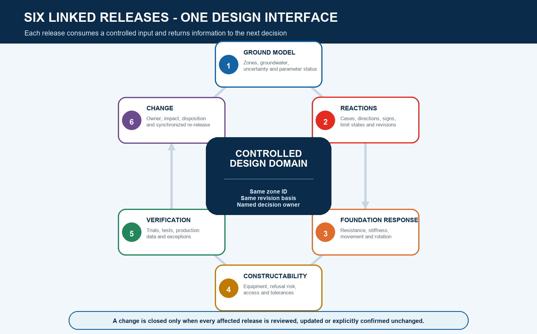
2. Use six linked releases instead of one final handoff
The interface is a loop, not a one-way transfer from geotechnical to structural. The ground model creates design domains. Structural reactions describe demand at supports. Foundation response converts ground and element behavior into resistance and serviceability information. Constructability checks whether the concept can be installed with the proposed equipment and tolerance. Verification tests selected assumptions. Change control returns new evidence to every affected release.
Each release needs common join keys: zone ID, support or table ID, coordinate system, load-case identifier, units, revision, status and owner. If one key is lost, the next calculation may be precise but attached to the wrong location or design state. Do not close a change merely because a revised drawing exists; close it when the affected releases are updated or explicitly confirmed unchanged.
3. Translate the ground model into structural design domains
A borehole map is not yet a structural design map. The geotechnical team should define zones that can be joined to the layout: boundaries, elevation or depth references, relevant ground units, groundwater conditions, obstructions, aggressive conditions, variability and confidence. Where interpolation is uncertain, show the uncertainty rather than extending a single investigation point across an entire array.
The European Commission's JRC guidance on assembling a Ground Model describes a site-specific representation built from investigations and other information, progressively upgraded as knowledge increases. Its companion guidance on representative values distinguishes measured, derived, representative, characteristic and design values. Those terms belong to the adopted project framework; they should not be collapsed into one unlabeled spreadsheet column.
| Ground-model output | What the structural/foundation team needs | Control question |
|---|---|---|
| Zone geometry | Map boundary, depth/elevation range, coordinate basis and exceptions | Can every support be assigned to a zone without guessing? |
| Ground units | Relevant layers, variability, obstructions and expected transitions | Which mechanism or installation risk changes by unit? |
| Water / drainage | Observed levels, variation, perched conditions and data dates | Which design, durability or installation assumptions depend on water? |
| Parameter status | Observation source, derivation, selected value, unit, limit state and owner | Is the value suitable for the stated calculation and stage? |
| Uncertainty / hazard | Coverage gaps, sensitivity, adverse conditions and required confirmation | What decision remains provisional, and what closes it? |
4. Issue structural reactions as an intelligible data set
Foundation design needs more than the largest vertical force. Issue reactions at the defined foundation or support reference point, with axes, sign convention and units. Retain compression, uplift, shear and moment components for each relevant load combination or response case. Identify ultimate and serviceability use, operating and stow states where applicable, and whether listed values occur together. A maximum assembled from different cases is not automatically a physically compatible design action.
ASCE/SEI 7-22 publicly describes environmental loads and load combinations, including provisions relevant to ground-mounted solar facilities. The adopted jurisdiction, code edition and project designer still control the actual actions and combinations. A module or tracker product rating is not a substitute for the site's structural design basis.
| Reaction-schedule field | Required meaning |
|---|---|
| Identity | Project, zone, table/support ID, node/reference point and drawing/model revision |
| Case | Load combination or response case, ULS/SLS purpose, operating/stow condition and compatibility |
| Components | Axial, shear and moment components with axis diagram, sign convention and units |
| Geometry | Support coordinates, base elevation, inclination, eccentricity and restraint assumptions |
| Performance | Settlement, differential movement, lateral displacement or rotation criteria where applicable |
| Status | Preliminary/approved, issue date, originator, checker, assumptions and next required update |
5. Return foundation response—not a single capacity number
The foundation team should return information the mounting model can use. Resistance may depend on direction, load interaction, ground zone, installation method and element configuration. Serviceability response may require axial, lateral or rotational stiffness, movement at a stated load level, differential behavior or a bounded nonlinear model. Constructability may limit section size, embedment, installation angle, equipment access or tolerance even when a calculation appears adequate.
Do not treat soil stiffness as one universal spring or “allowable bearing” as a complete foundation definition. State whether the response is a preliminary sensitivity, a design value, a test-calibrated relationship or an acceptance limit. Identify the analysis point and sign convention, as well as behavior outside the intended range. If the mounting model needs a matrix or curve, a single scalar value may hide coupling or directionality.
| Returned item | Minimum content | Mounting-model use |
|---|---|---|
| Resistance | Mode, direction, combination, zone, element configuration, basis and factors | Strength and stability checks |
| Stiffness / response | Reference point, direction, load range, curve or value, uncertainty and revision | Support flexibility and load redistribution |
| Movement / rotation | Predicted or limiting values, differential basis and applicable case | Geometry, module, drive and connection serviceability |
| Constructability | Equipment, access, tolerances, refusal/obstruction route and permitted alternatives | Detailing, layout and installation plan |
| Durability | Exposure/ground chemistry basis, material/protection assumptions and inspection needs | Design life, interfaces and maintenance evidence |
6. Recheck the mounting structure with support behaviour
Once the foundation response is available, return it to the PV support structure model. Check whether support flexibility changes member forces, connection demand, table twist, tracker alignment, drive behavior or serviceability. Review differential settlement and rotation across a table rather than only the movement of one isolated support. Confirm that the foundation reference point matches the structural node and that any baseplate, post projection or eccentricity between them is modeled consistently.
Reconcile every support ID and coordinate with the current layout and ground-zone map.
Apply the returned response to the stated direction, load range, limit state and revision.
Check member and connection strength together with geometry and serviceability effects.
Reissue reactions if the foundation location, stiffness, restraint, embedment or layout changes.
Record sensitivities when ground or support behavior remains preliminary.
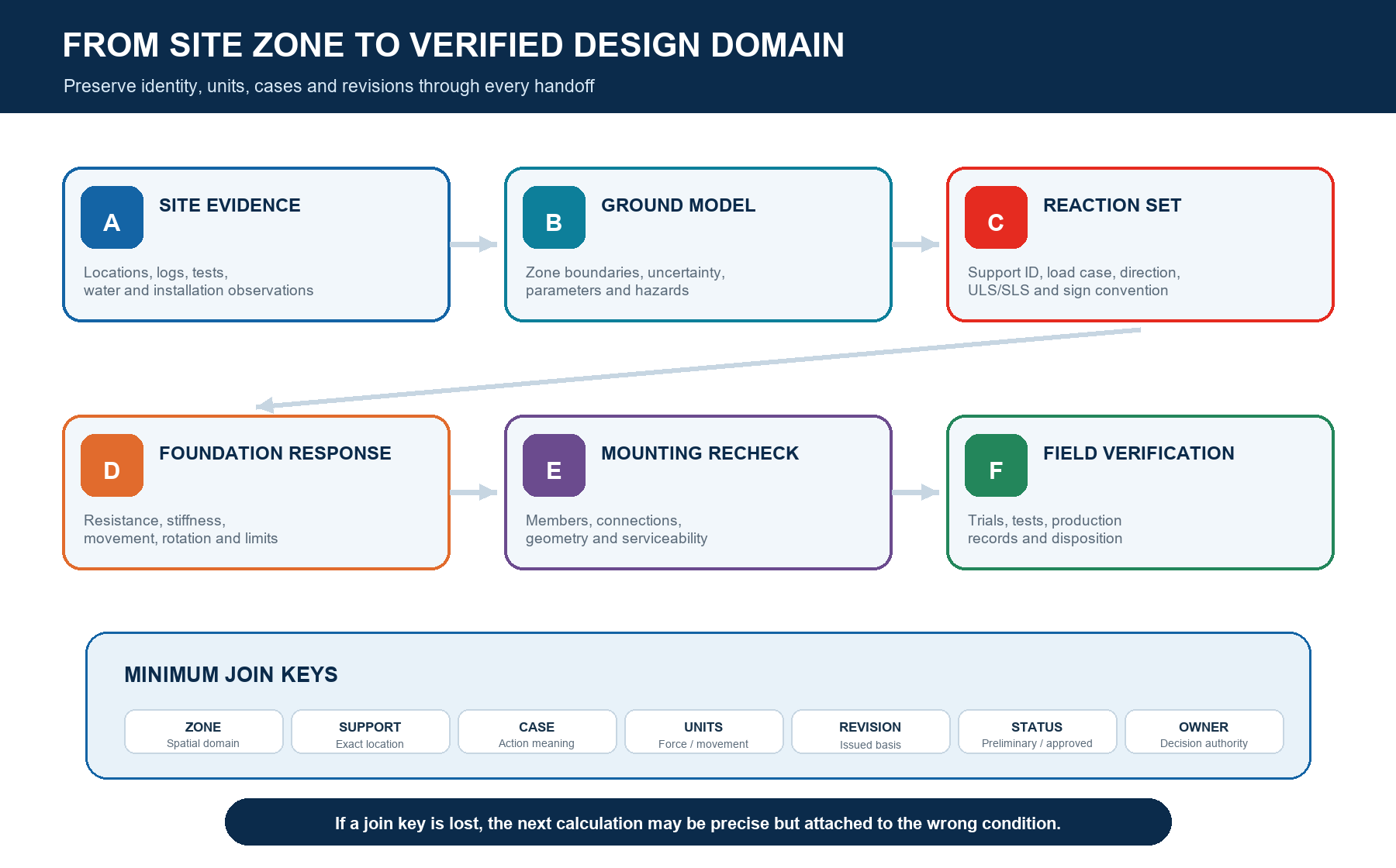
7. Link trial installation and load testing to assumptions
Field verification should answer pre-agreed questions. A trial installation can test equipment access, installation sequence, refusal risk, achievable geometry and record quality for the tested conditions. A load test can characterize a defined load-movement response for an identified element and ground condition. Production records can show whether installation observations remain within the approved control route. None of these automatically represents every foundation or zone.
ISO 22477-1:2018 provides a public scope for maintained static axial compression testing of piles. IEC 62817:2014+A1:2017 addresses design qualification of solar trackers and their systems. A product qualification result and a site foundation test answer different questions; neither removes the need for a site-specific interface and approved interpretation route.
| Evidence | Question it can support | What it does not prove alone |
|---|---|---|
| Trial installation | Feasibility, equipment, sequence, refusal/obstruction and achievable tolerance | Design resistance across untested zones |
| Foundation load test | Defined load-movement response for the tested element and conditions | All load modes, all configurations or long-term site performance |
| Installation record | Identity, actual configuration, location, equipment and recorded observations | Capacity without a project-specific validated relationship |
| Survey / as-built | Position, elevation, inclination and geometry against defined tolerances | Ground behavior or structural adequacy by itself |
8. Control production data and field exceptions
Production should not be a separate information stream. Link each installed element to its design zone, configuration and applicable drawing. Record the fields required by the approved installation plan—such as location, date, equipment, element identity, achieved geometry, relevant installation observations and exceptions—without implying that one observation is a universal capacity measurement.
When refusal, unexpected ground, excessive deviation, damaged protection, groundwater or a geometric conflict appears, preserve the original record and open a unique exception. The disposition should identify affected supports, the technical reviewer, the chosen action, any retest or redesign, and every document requiring update. Do not solve a field problem with an undocumented length, section, location or installation change.

9. Manage changes through a two-way register
A change register should start at the first affected decision and travel both ways. A module or table geometry change can alter reactions. A new ground zone can alter foundation response and quantity. A trial installation can reveal a constructability limit that changes the foundation concept and rack detail. A drainage or grading change can affect ground levels, water conditions, exposure and installation access.
| Change trigger | Structural review | Geotechnical/foundation review | Close when |
|---|---|---|---|
| Module/table geometry | Loads, spans, restraint, reactions and serviceability | Support demand, layout and foundation response | Both schedules share one approved revision |
| Ground-zone boundary | Affected table/support IDs and redistribution sensitivity | Parameters, concept, quantities and verification coverage | Layout, zone map and foundation schedule reconcile |
| Foundation configuration | Node, stiffness, eccentricity, connection and tolerances | Resistance, installation and durability basis | Model, drawings, BOM and method are re-released |
| Field exception | Affected support/table and downstream structural consequence | Cause, usable evidence, repair/retest/redesign route | Named authority signs disposition and records update |
10. Use decision gates instead of “geotechnical complete”
“Geotechnical complete” hides the intended use. Replace it with gates that state which decision may proceed. A preliminary ground model may support sensitivity studies but not fabrication. A verified zone and reaction set may support final foundation selection but still await trial installation. A signed design basis may release drawings while selected construction zones remain subject to hold points.
| Gate | Entry evidence | Permitted output | Hold point |
|---|---|---|---|
| Screening | Location, concept, preliminary ground and environmental information | Options, sensitivities and investigation questions | No final foundation or production release |
| Zoned basis | Controlled layout, ground-model zones and preliminary reactions | Zone-by-zone concept and verification plan | Open coverage, parameter or constructability gaps |
| Design issue | Approved reactions, selected parameters, response and performance checks | Controlled calculations and drawings | Unresolved interface, change or verification condition |
| Construction release | Approved method, trials/tests where required and closed design actions | Installation by zone/configuration | Exception or change outside the approved route |
| Handover | As-built, production, test, deviation and signed disposition records | Traceable completion package | Missing identity, review or unresolved nonconformance |
11. Prevent common interface failures
The ground report is issued without a layout-linked zone map or stated confidence.
Reaction maxima are copied without load cases, signs, units, axes or compatibility.
One generic soil spring or capacity is applied to every support without a defined domain.
Foundation resistance is checked but support settlement, lateral movement or rotation is omitted.
A foundation or post detail changes without reissuing the structural model and reactions.
Trial installation or load-test evidence is detached from element identity, zone and configuration.
Installation torque is treated as proof of capacity without an approved project correlation.
A field exception is repaired physically but never closed in the calculations, drawings or records.
Preliminary values lose their status and appear in fabrication or construction documents.
The supplier review is treated as a substitute for project structural or geotechnical responsibility.
12. Assemble one combined design basis
The combined design basis should be an indexed set, not one oversized report. Each item may remain owned by its discipline, but the index shows the current approved relationship. Include the project basis, layout and zone map; structural model and reaction schedule; ground investigation and interpretation; selected parameter register; foundation analysis and response schedule; constructability assessment; trial/test plan and records; durability basis; interface and change registers; drawings, BOM and signed release status.
Assign one interface coordinator to run periodic reconciliation without taking technical responsibility away from either designer. The reconciliation should compare support counts, zone assignments, coordinates, reaction revisions, foundation configurations, open assumptions and field dispositions. Record mismatches as actions with an owner and required date. A meeting note that says “aligned” is weaker than a controlled comparison showing which two revisions were checked and which exceptions remain open.
| Index block | Controlled evidence |
|---|---|
| Basis / geometry | Codes, stage, units, coordinates, layout, table/support IDs, zones and revisions |
| Demand | Structural model assumptions, actions, combinations, reaction schedule and serviceability criteria |
| Ground / response | Investigation, model, selected values, uncertainties, foundation response and limitations |
| Construction / verification | Installation method, trials, test records, production controls and exception register |
| Release / change | Responsibility matrix, approvals, superseded versions, open items and signed dispositions |
13. What to send East Baoyu
For an efficient supplier engineering review, send the controlled project basis and a specific decision question. Include the current module and mounting architecture, layout with support IDs, design actions and reaction schedule, ground investigation and zone map, foundation concept, target materials/durability, performance criteria, installation constraints, test or trial requirements, programme, quantity by zone and open changes.
| Submission | Minimum content |
|---|---|
| Project basis | Country/site, coordinates, jurisdiction, code route, design stage, units and requested decision |
| Mounting / layout | Module, fixed/tracker/flexible concept, table geometry, support IDs, zones and revision |
| Structural | Actions, combinations, reaction schedule, axes/signs, serviceability criteria and model status |
| Ground / foundation | Investigation, ground model, selected-value status, concept, response and uncertainties |
| Field / commercial | Equipment/access, trials/tests, quantity by zone, delivery programme and open changes |
Review East Baoyu's Solar Mounting, Screw Piles, Quality & Manufacturing and Certification & Evidence Center pages before requesting a project-specific review. East Baoyu can clarify supplier-side configuration, drawings, production evidence and open interfaces within an agreed scope. The project's qualified designers retain responsibility for design inputs, calculations, testing interpretation, acceptance and construction release.
Request an engineering review
Send the layout, support IDs, design stage, reaction schedule, ground-model zones, foundation concept, installation constraints, available test evidence and exact review question. East Baoyu will identify usable supplier-side information, missing joins and the appropriate review route without silently converting preliminary assumptions into approvals.

Questions? Chat with East Baoyu on WhatsApp. Fast reply on capacity, price, configuration and available product videos.
Open WhatsApp: +86 130 1228 3281
| Contact | Official detail |
|---|---|
| info@eastbaoyu.com | |
| Phone | +86 22 28352066 |
| +86 130 1228 3281 | |
| Website | https://eastbaoyu.com/contact/ |
Email the engineering review package: info@eastbaoyu.com
Frequently asked questions
What geotechnical inputs are needed for solar mounting design?
The answer depends on the mounting architecture, foundation concept, design stage and site. A controlled package commonly identifies ground and groundwater conditions, design zones, relevant hazards and obstructions, parameter status, uncertainty, constructability and required verification. Investigation quantity, depth and methods must be selected by the project's qualified team rather than copied from a universal list.
Should geotechnical or structural design be completed first?
Neither discipline should wait for a single final handoff. Start with a preliminary layout, ground model and reaction basis, then iterate. Structural demand informs the geotechnical questions; foundation response informs the structural model. Release gates should state which decisions are allowed while inputs remain preliminary.
Can one foundation capacity be used across the whole solar site?
Only when the responsible designers justify the applicable design domain and all relevant conditions. Capacity may vary with ground zone, element configuration, installation, load direction and limit state. Stiffness, movement, rotation, constructability and durability can govern even when a headline resistance value appears adequate.
How should structural reactions be issued to the foundation designer?
Provide support identity and reference point, coordinates, axes, sign convention, units, load case or combination, ULS/SLS purpose, component compatibility, geometry, relevant performance criteria, model revision, status and assumptions. Avoid a table of unlabeled maxima assembled from different cases.
Do trial installation and load testing close the design interface?
They can verify defined assumptions when their purpose, coverage, configuration, method and acceptance route are approved in advance. A trial installation does not by itself prove design resistance, and one load test does not automatically represent every zone, foundation, load mode or long-term condition.
When must a foundation or ground change return to the structural model?
Return it whenever support position, elevation, inclination, stiffness, restraint, eccentricity, connection, movement, rotation, configuration or applicable zone changes. The structural reviewer should assess affected members, connections, geometry, serviceability and reactions, then issue or confirm the synchronized revision.
Related East Baoyu resources
Ground Screw Selection from Site Investigation | Installation Torque and Ground Screw Capacity
Solar Tracker Wind Load and Stow Strategy | Fixed Versus Tracking PV Energy Comparison
Flexible PV Mounting Span, Pretension and Dynamics | Quality & Manufacturing
Certification & Evidence Center | Product Documents & Buyer Guides
Engineering Research & Methods | Engineering Articles
References and scope notes
Sources were checked on 28 July 2026. Public scopes and guidance are paraphrased. This article does not prescribe universal investigation spacing or depth, soil values, safety factors, reaction combinations, stiffness, movement limits, foundation configuration, test quantity or acceptance criteria. It is not a project design, geotechnical report, test procedure, method statement, safety plan or construction release.
JRC – Assembling the Ground Model and the derived values (2024) | JRC – Representative values from derived values for EN 1997 verification (2025)
FHWA-NHI-16-072 – Geotechnical Site Characterization | FHWA GEC 12 – Design and Construction of Driven Pile Foundations
FHWA-HIF-18-031 – Laterally Loaded Deep Foundations | ASCE/SEI 7-22 – Minimum Design Loads and Associated Criteria
ASCE MOP 162 – Design and Construction of Solar PV Structures | ISO 22477-1:2018 – Static compression testing of piles
IEC 62817:2014+A1:2017 – Design qualification of solar trackers
References, disclosure and change record
References and further verification
- https://eurocodes.jrc.ec.europa.eu/publications/assembling-ground-model-and-derived-values
- https://eurocodes.jrc.ec.europa.eu/publications/determination-representative-values-derived-values-verification-limit-states-en-1997
- https://www.asce.org/publications-and-news/codes-and-standards/asce-sei-7-22
- https://www.iso.org/standard/70807.html
- https://webstore.iec.ch/en/publication/61127
- https://eastbaoyu.com/solar-mounting/
- https://eastbaoyu.com/screw-piles/
- https://eastbaoyu.com/quality/
- https://eastbaoyu.com/evidence-center/
- https://wa.me/8613012283281
- https://wa.me/8613012283281?text=Hello%20East%20Baoyu%2C%20I%20would%20like%20an%20engineering%20review%20of%20the%20geotechnical-structural%20interface%20for%20a%20solar%20mounting%20project.
- https://eastbaoyu.com/ground-screw-selection-from-site-investigation/
- https://eastbaoyu.com/installation-torque-and-ground-screw-capacity/
- https://eastbaoyu.com/solar-tracker-wind-load-and-stow-strategy/
- https://eastbaoyu.com/fixed-versus-tracking-pv-energy-comparison/
- https://eastbaoyu.com/flexible-pv-mounting-span-pretension-dynamics/
- https://eastbaoyu.com/downloads/
- https://eastbaoyu.com/research-methods/
- https://eastbaoyu.com/articles/
- https://eastbaoyu.com/contact/
- https://highways.fhwa.dot.gov/sites/fhwa.dot.gov/files/FHWA-NHI-16-072.pdf
- https://www.fhwa.dot.gov/engineering/geotech/pubs/gec12/nhi16009_v1.pdf
- https://www.fhwa.dot.gov/engineering/geotech/pubs/hif18031.pdf
- https://sp360.asce.org/personifyebusiness/Merchandise/Product-Details/productId/331623136
Disclosure: East Baoyu manufactures and supplies products discussed on this website. Structured drafting tools may assist research and editing, but technical claims, project inputs and release decisions require qualified review under the applicable project responsibilities.
Version 1.0: Initial scheduled publication in the East Baoyu engineering knowledge-base batch.
View the public Content Change Log · Corrections: info@baolaipipes.com