

Authorship, review and evidence boundary
- Technical review
- East Baoyu Engineering Editorial Team
- Reviewed
- 2026-07-29
- Scope
- General engineering and procurement guidance. This article is not a project-specific design, capacity statement, certificate, warranty, code interpretation or contract requirement.
Evidence basis: Official and public references identified in the article, together with original editorial diagrams. Project values and release decisions require qualified review under the applicable project responsibilities.
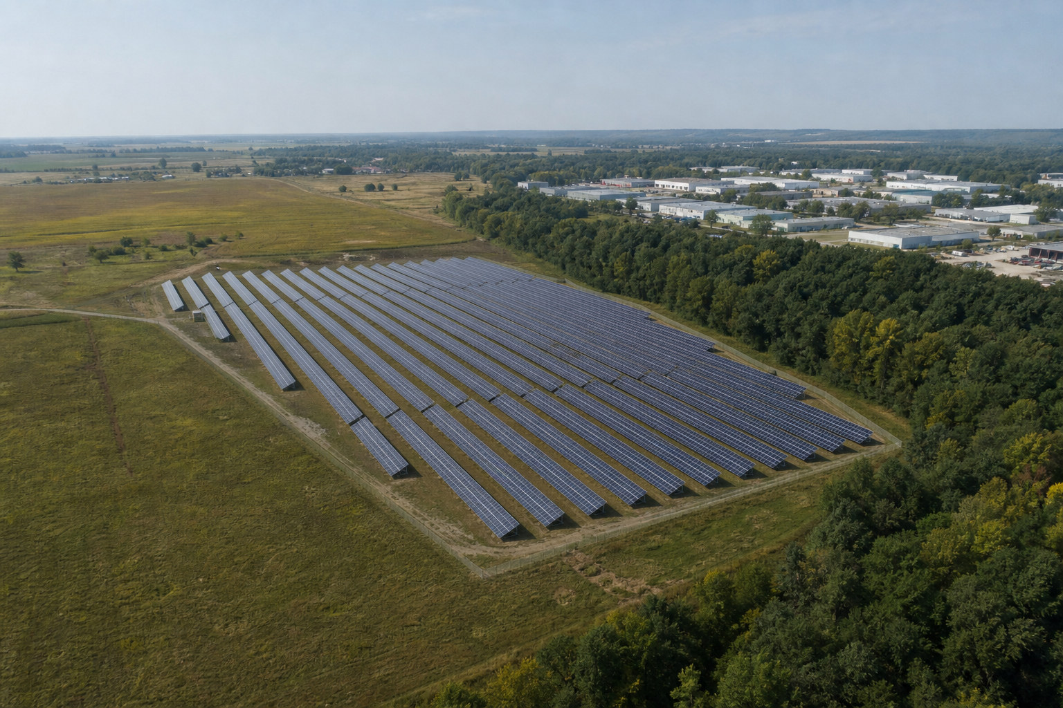
Read the Editorial PolicyStand near the centre of a proposed array and turn 180 degrees. One view may be uninterrupted farmland; the opposite view may contain a tree belt, warehouses or a growing settlement. Calling the whole address "open terrain" or "suburban" discards the direction that gives the surrounding surface its role in wind design. The practical record must preserve where the wind comes from, how far the relevant surface condition extends and which governing procedure converts that evidence into a design input.
Terrain category for solar mounting should therefore be selected under the project's adopted wind standard, edition, jurisdictional amendments and approval route. Fix the array reference point, design height, wind direction or sector, required upwind extent, physical roughness description, transitions, evidence date and future land-use assumptions before assigning a framework-specific label. The label alone is not a site record, and a satellite image alone is not an engineering decision.
1. Read the site by wind direction, not by address
Surface roughness describes the upwind landscape that modifies the wind profile approaching the structure. The relevant landscape can change with direction, even when the project boundary does not. Open water, crop fields, scattered buildings, continuous tree cover and dense development do not form one interchangeable site adjective. A directional review retains those differences until the adopted method says how they are to be classified and combined.
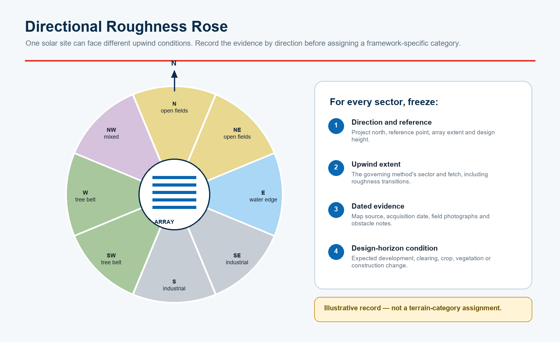
Begin with project north, the complete proposed array extent and a reference point or set of reference points. Draw the wind directions or sectors required by the governing route and trace outward through the upwind surface. Do not start by choosing the category that appears most familiar. Start with observations: land-cover type, obstacle height, spacing, density, continuity, water edges, cleared strips, settlements and visible transitions. This sequence keeps the evidence usable if the standard, layout or design height changes.
2. Lock the governing framework before naming a category
Terms that sound similar across ASCE, Eurocode and AS/NZS practice are not automatic equivalents. Category names, roughness parameters, direction-sector rules, transition treatment, reference heights and national choices belong to their own adopted procedures. A cross-code table can help a team identify questions, but it must not be used as a conversion chart. The engineer should identify the contractual standard, edition, National Annex or local amendments, authority requirements and any owner-specific basis before a category is released.
ASCE describes ASCE/SEI 7-22 as a minimum design-load standard and notes that the edition modernized provisions including ground-mounted solar facilities. The ASCE Hazard Tool documents its U.S. wind-speed output as a three-second gust at 33 ft (10 m) for Exposure C. That mapped hazard output is not the same record as the project exposure decision. The wind speed can come from the tool while the directional surface assessment is retained and approved separately.
Confirm the edition and scope using the official ASCE/SEI 7-22 page and review the public ASCE Hazard Tool API documentation. Do not copy a U.S. exposure term into another contractual framework.
| Framework | Public control point | Project confirmation | Do not infer |
|---|---|---|---|
| ASCE route | ASCE 7 edition and mapped-hazard basis | Adopted code, risk category, exposure procedure and project amendments | Hazard-tool wind speed automatically selects project exposure |
| Eurocode route | EN 1991-1-4 wind actions | Locally adopted edition, National Annex and transition rules | A roughness value from a worked example is a universal default |
| AS/NZS route | AS/NZS 1170.2:2021 wind actions | Contract jurisdiction, amendments, terrain/height and shielding route | Its terminology converts directly to ASCE or Eurocode labels |
| Project specialist route | Approved study, wind tunnel or other contractual method | Scope, geometry, terrain model, operating states and acceptance | A specialist result removes every code and interface check |
For Eurocode work, confirm both the adopted edition and the National Annex. The European Commission Joint Research Centre identifies EN 1991-1-4 within Eurocode 1 and publishes the second-generation transition programme: national implementation/publication is targeted by 30 September 2027, with withdrawal of conflicting first-generation national standards by 30 March 2028. Projects spanning that period need an explicit edition decision, not an assumption based on a generic web article.
See the JRC pages for Eurocode 1 actions on structures and the second generation of the Eurocodes. For Australia and New Zealand, the publisher's AS/NZS 1170.2:2021 update specifically notes consideration of solar farms.
3. Fix the design reference point, array extent and height
A sector drawn from the wrong point can cross a different land-cover transition. Record the coordinate system, project north, boundary, current and planned array envelope, representative points and the height used by the governing method. Large or elongated solar sites may need more than one assessment point because the upwind environment at the west edge can differ from that at the east edge. The engineer should decide whether one point represents the site or whether zones are required.
Freeze the layout revision used for the assessment. A later expansion, raised tracker geometry, relocated substation or changed perimeter can alter the relevant reference points and wind-context interfaces. The released record should include the layout drawing number and revision, the design-height definition and the date on which the physical surroundings were reviewed. Without those fields, a category cannot be reproduced.
4. Build the Directional Roughness Rose
The Directional Roughness Rose is a project control sheet, not a new design standard. For every required direction or sector, it records the reference point, bearing limits, upwind extent, land-cover sequence, obstacle description, transitions, data sources, field evidence, known future changes, adopted framework and approval status. It gives the category decision a visible evidence trail and exposes sectors that remain unresolved.
| Sector record field | Minimum content | Why it matters |
|---|---|---|
| Direction and geometry | Bearing range, project north, reference point, array extent and design height | Keeps the evaluated path tied to the current design |
| Upwind surface | Physical cover, obstacles, density, continuity and transition distances | Preserves observations before a framework label is applied |
| Evidence identity | Source, acquisition date, resolution, licence, field date and photograph direction | Shows what was actually reviewed and when |
| Decision control | Standard, edition, local route, category/result, owner, reviewer and revision trigger | Makes the released input auditable and change-controlled |
5. Follow the required upwind sector and fetch
Do not invent one fixed radius for every project. The width of a direction sector, the distance or fetch to inspect, the role of structure height and the treatment of roughness changes must come from the adopted procedure. The record should show the full required upwind path, including any transition that crosses it. A neatly cropped image around the fence line is incomplete if the governing extent reaches beyond the crop.
Where access or imagery is limited, mark the sector as open rather than filling the gap with a convenient label. Identify what is missing, who must provide it and whether the design or procurement package is held. The conservative response to uncertainty is a project engineering decision; it is not automatically the category that looks roughest, because different procedures and load effects do not guarantee a universal monotonic shortcut.
6. Describe physical roughness before assigning a label
The description should be specific enough for another reviewer to understand the physical setting without seeing the selected category. Record the dominant cover and meaningful obstacles: approximate height, plan size, spacing, density, continuity and distance from the reference point. Distinguish seasonal crops from permanent tree cover, isolated buildings from continuous development, and a water edge from open land. Record uncertainty instead of disguising it with a precise category name.
FEMA's public wind-resistance compilation illustrates direction sectors and surface-roughness concepts in a U.S. code context. FEMA P-804 provides accessible landscape examples under an ASCE 7-22 residential retrofit scope. They can help teams understand the idea, but neither document is a substitute for the project's solar design procedure, adopted code or engineer's assessment.
Use the scope labels when consulting the FEMA wind-resistance compilation and FEMA P-804. Public examples explain concepts; the contract and adopted standard control the assignment.
7. Keep roughness, topography, shielding and array aerodynamics separate
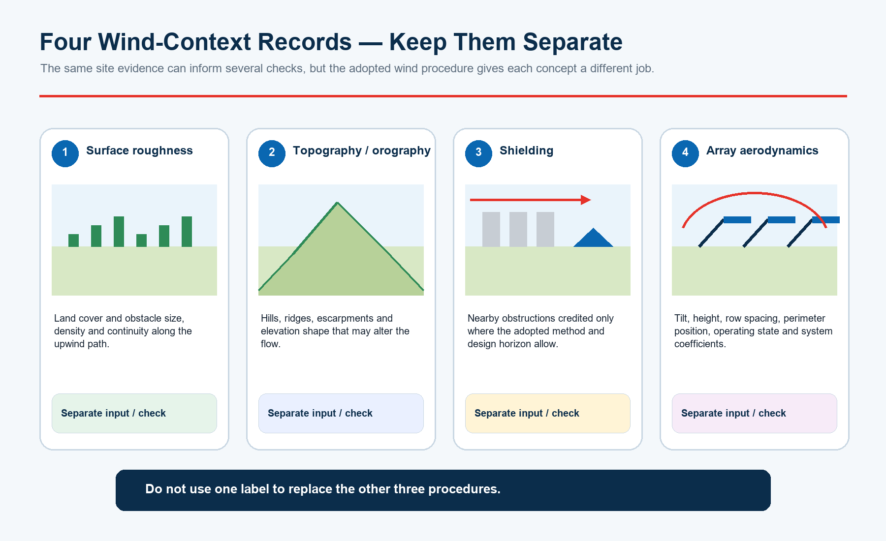
Four wind-context records can use some of the same site evidence but perform different jobs. Surface roughness addresses land cover and obstacle fields along the upwind path. Topography or orography addresses hills, ridges, escarpments and elevation shape. Shielding addresses the credit, if any, permitted for nearby obstructions under the adopted method and design horizon. Array aerodynamics addresses the panels or trackers themselves: tilt, height, row spacing, perimeter position, operating state and applicable coefficients.
A tree belt should not silently serve as roughness classification, topographic correction, shielding credit and array coefficient all at once. Likewise, a terrain category does not replace a required wind-tunnel study, computational study, dynamic assessment or tracker operating-state evaluation. Record each input and check separately, then show where the approved wind-design basis connects them.
The U.S. Geological Survey 3D Elevation Program standards concern elevation data, while land-cover datasets describe a different evidence class. NREL/National Laboratory of the Rockies research on wind loading and instability in tracking PV arrays also underscores the role of direction, orientation, layout and site-specific factors.
8. Resolve mixed terrain and transitions
Mixed terrain is not resolved by averaging category names. Mark each transition along the required upwind path and record its distance from the design reference. Then apply the adopted framework's rule for changes in roughness, sector boundaries and relevant height. If a sector contains open fields followed by dense development, the order and extent of those surfaces matter. A colour-filled plan should therefore retain the distances and underlying observations, not just the final colour.
Where adjacent sectors reach materially different decisions, keep both records and make the structural calculation or specialist model consume the direction-specific inputs as required. Where a boundary is uncertain, define the uncertainty range and the closure action. Do not claim that selecting the visually roughest condition is always conservative: the governing direction, pressure sign, system response and standard-specific equations can change the result.
9. Verify remote data with dated field evidence
Remote imagery and land-cover data are efficient screening tools. ESA WorldCover provides global 10 m land-cover products for 2020 and 2021. In the United States, the USGS Annual National Land Cover Database supports land-cover and change review. These products can identify possible transitions and help plan a site visit, but classification age, resolution, seasonal effects and mapping classes may not match the physical descriptors or fetch required by a structural wind procedure.
Retain metadata and limitations when using ESA WorldCover or the USGS Annual National Land Cover Database. Treat them as screening and historical context, not an automatic category assignment.
| Evidence | Valid use | Important limitation |
|---|---|---|
| Satellite or aerial imagery | Trace broad land cover, transitions and access targets | Date, season, oblique height and small obstacles may be uncertain |
| Land-cover dataset | Screen sectors and detect possible change | Map class is not a structural terrain category |
| Elevation model / survey | Support topography and reference geometry | Does not describe obstacle density or roughness by itself |
| Direction-tagged field record | Verify obstacle type, height, density, continuity and recent change | Limited access or visibility must be stated |
| Planning / land-use record | Identify approved development, clearing or construction | Approval does not guarantee timing or final built form |
10. Test the design-horizon condition
Wind design concerns the structure's service period, not only the landscape visible on the survey date. Review approved developments, planned clearing, crop or vegetation cycles, forestry, temporary construction, new roads and adjacent solar phases. A tree belt that is credited today may be removed; open land may become built development. The responsible engineer should define which foreseeable conditions are evaluated and which assumptions trigger reassessment.
Record the evidence date and design-horizon basis next to every directional decision. If the classification depends on property outside the owner's control, say so explicitly. The project may need a no-credit approach, a binding land-use control, multiple cases or another approved treatment. This article does not prescribe which response is correct; it requires the dependency to be visible before procurement locks the mounting system.
11. Release a Terrain Evidence Pack
Release the category decision as a controlled package rather than a lone spreadsheet cell. The minimum pack contains a georeferenced plan; dated imagery with source, resolution and licence; direction-tagged field photographs and obstacle notes; a design-horizon change record; the framework decision with edition, local choices, sectors and fetch; and an approval/revision sheet naming the owner, reviewer, issue date, assumptions, holds and trigger for reassessment.
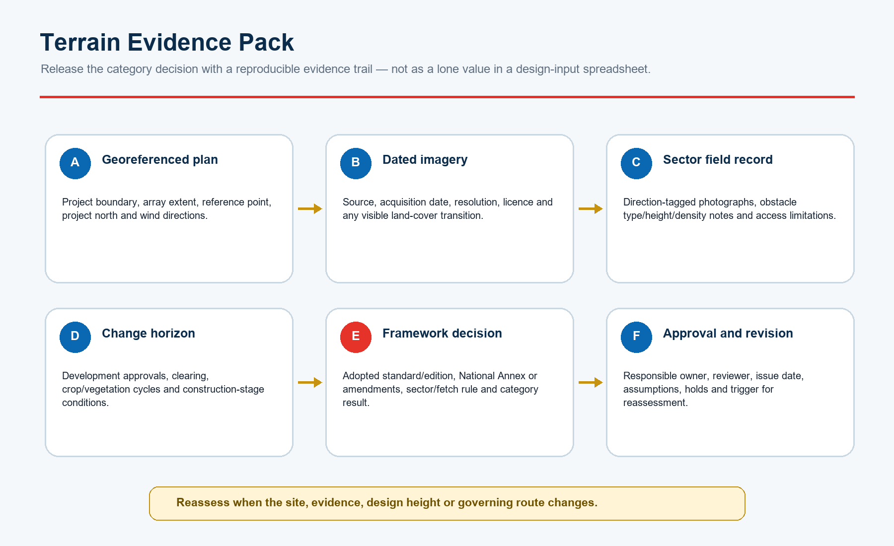
Name files and photographs by project, reference point, direction, date and revision. Preserve the original imagery and field notes alongside annotated derivatives. The released summary should identify unresolved sectors and interfaces, not hide them. When the layout, design height, evidence, surroundings or governing route changes, reopen the affected record and issue a new revision rather than overwriting the decision history.
12. Connect the released input to solar mounting design
The approved terrain or roughness input must connect to the same wind-design basis used for array geometry, module dimensions, tilt or tracker states, row spacing, support height, site elevation, wind hazard, topographic treatment, pressure coefficients, load combinations and foundation reactions. Record document numbers and revisions at this interface. A correct terrain assessment can still be misused if the structural model consumes an older layout or a generic coefficient route.
For procurement, transmit the controlling input, its revision and limitations with the design reactions. Do not ask a mounting supplier to infer terrain from a project address or a single screenshot. East Baoyu can review the completeness of supplied engineering inputs and the product/interface route, but the project engineer and governing approval process control the site classification and structural design.
Use the East Baoyu Solar Mounting Systems, Engineering Articles and Contact pages to frame the product and engineering-input discussion.
13. Use rejection conditions at project gates
| Rejection condition | Why the input is not releasable | Required closure |
|---|---|---|
| One category for the address; no directions | Upwind conditions and governing sector are not traceable | Issue directional sectors from defined reference point(s) |
| Map screenshot with no date or source | Evidence identity, age, resolution and licence are unknown | Provide original source metadata and field verification |
| Category copied across standards | Terminology and procedures may not be equivalent | Confirm the adopted framework and perform its own assessment |
| Roughness used as topography or shielding | Separate wind-context checks have been collapsed | Release individual inputs/checks under the approved design basis |
| Future land-use dependency not assessed | Current surroundings may not persist through the design horizon | Document cases, controls, assumptions and reassessment trigger |
| Layout or height changed after approval | Reference point, fetch or structural interface may have changed | Reassess affected sectors and reissue the evidence pack |
Apply these conditions at wind-design-basis approval, mounting-system quotation, structural calculation release and design-change review. A held input is not a failed project; it is an identified gap with an owner and closure path. Release only when the responsible reviewer can reproduce the direction, physical evidence, framework decision and revision consumed by the design.
14. What to send East Baoyu
For an engineering-input review, send the project location and jurisdiction; adopted wind standard and edition; National Annex or amendments; site boundary and latest array layout; project north and coordinates; module or tracker geometry; support height; design life; available wind basis; grading and topographic survey; directional land-cover plan; dated imagery; field photographs; adjacent development information; and the engineer's released terrain or roughness record. Identify preliminary, approved and unresolved inputs.
If no terrain decision has been released, send the factual evidence and name the responsible project engineer. East Baoyu can identify missing interface inputs and discuss mounting-system supply, but this article does not assign a project terrain category, calculate wind loads, approve a site, certify compliance or promise a product capacity, price or schedule.
Request an engineering input review
Send the current layout, governing wind basis, directional surface evidence, design height, future land-use notes and released engineering input. East Baoyu can help structure the mounting-system interface and identify missing records before design or procurement proceeds.

Open WhatsApp: +86 130 1228 3281
| Contact | Official detail |
|---|---|
| info@eastbaoyu.com | |
| Phone | +86 22 28352066 |
| +86 130 1228 3281 | |
| Website | https://eastbaoyu.com/contact/ |
Email the project inputs: info@eastbaoyu.com
Frequently asked questions
Can one terrain category be used for an entire solar farm?
Only if the adopted procedure and project assessment support that decision. Large sites and different wind directions may require multiple reference points, sectors or directional results.
Is satellite imagery enough to select terrain category?
Not by itself. Imagery is useful screening evidence, but its date, resolution, season and classification must be known and material observations should be verified with current field or approved land-use evidence.
Are ASCE exposure categories equivalent to Eurocode terrain categories?
No universal equivalence should be assumed. Each framework has its own definitions, parameters and procedures. Apply the contractual standard, edition, National Annex or amendments directly.
Is the roughest-looking category always conservative?
No universal rule makes that shortcut safe. Direction, load effect, system response and the adopted equations can alter the governing result. The project engineer should evaluate uncertainty explicitly.
Does a tree belt automatically provide shielding credit?
No. Any shielding treatment must be permitted by the adopted method and credible for the design horizon. Record it separately from surface roughness and topography.
When should the terrain assessment be revised?
Reassess when the array extent, reference point, design height, surrounding land cover, evidence, approved development or governing standard route changes enough to affect the released decision.
Related East Baoyu resources
Solar Mounting Systems | Engineering Articles
Evidence Center | Contact East Baoyu
Wind Speed Definition and Unit Conversion | Topographic Survey Requirements for Solar Mounting Design
Solar Mounting Site Input Checklist | Research & Methods
References and scope notes
Official public sources were checked on 28 July 2026 and are paraphrased within their public scope. Licensed standards and paywalled text were not reproduced. Confirm the project contract, jurisdiction, adopted standard and edition, National Annex, amendments, authority requirements, approved wind-design basis, site survey, land-use information and specialist studies. This guide is an input-control method, not a terrain assignment, wind-load calculation, topographic study, wind-tunnel report, compliance certificate or commercial commitment.
ASCE/SEI 7-22 official page | ASCE Hazard Tool API documentation
ASCE 7-22 update announcement | FEMA wind-resistance compilation
FEMA P-804 (2023) | JRC Eurocode 1
JRC wind worked example | JRC second-generation Eurocodes
Standards Australia AS/NZS 1170.2:2021 update | New Zealand CodeHub AS/NZS 1170.2:2021
ESA WorldCover | USGS Annual National Land Cover Database
USGS 3D Elevation Program standards | NREL/NLR PV tracker wind research
ASCE Solar PV Structures Committee | East Baoyu Solar Mounting Systems
References, disclosure and change record
References and further verification
- https://www.asce.org/publications-and-news/codes-and-standards/asce-sei-7-22
- https://www.asce.org/-/media/asce-images-and-files/publications-and-news/hazard-tool/hazard-tool-api-documentation.pdf
- https://eurocodes.jrc.ec.europa.eu/EN-Eurocodes/eurocode-1-actions-structures
- https://eurocodes.jrc.ec.europa.eu/second-generation-eurocodes
- https://www.standards.org.au/news/update-to-the-go-to-combined-wind-actions-standard
- https://www.fema.gov/sites/default/files/2020-07/2015-ibc-compilation-wind-resistance-provisions.pdf
- https://www.fema.gov/sites/default/files/documents/fema_p-804-wind-retrofit-guide-042023.pdf
- https://www.usgs.gov/ngp-standards-and-specifications/3d-elevation-program-standards-and-specifications
- https://esa-worldcover.org/en
- https://www.usgs.gov/centers/eros/science/annual-national-land-cover-database
- https://eastbaoyu.com/solar-mounting/
- https://eastbaoyu.com/articles/
- https://eastbaoyu.com/contact/
- https://wa.me/8613012283281
- https://wa.me/8613012283281?text=Hello%20East%20Baoyu%2C%20I%20would%20like%20to%20discuss%20terrain%20and%20surface%20roughness%20inputs%20for%20a%20solar%20mounting%20project.
- https://eastbaoyu.com/evidence-center/
- https://eastbaoyu.com/basic-wind-speed-conversions-solar-projects-avoiding-input-errors/
- https://eastbaoyu.com/topographic-survey-requirements-ground-mount-solar-structures/
- https://eastbaoyu.com/solar-mounting-design-input-checklist-epc-procurement/
- https://eastbaoyu.com/research-methods/
- https://www.asce.org/publications-and-news/civil-engineering-source/society-news/article/2021/12/01/newly-updated-minimum-design-loads-and-associated-criteria-for-building-and-other-structures-asce-sei-7-22-standard-now-available/
- https://eurocodes.jrc.ec.europa.eu/sites/default/files/2022-06/Kristensen_Hansen_2008.pdf
- https://codehub.building.govt.nz/resources/asnzs-1170-22021
Disclosure: East Baoyu manufactures and supplies products discussed on this website. Structured drafting tools may assist research and editing, but technical claims, project inputs and release decisions require qualified review under the applicable project responsibilities.
Version 1.0: Initial scheduled publication in the East Baoyu engineering knowledge-base batch.
View the public Content Change Log · Corrections: info@baolaipipes.com