

Authorship, review and evidence boundary
- Technical review
- East Baoyu Engineering Editorial Team
- Reviewed
- 2026-07-29
- Scope
- General engineering and procurement guidance. This article is not a project-specific design, capacity statement, certificate, warranty, code interpretation or contract requirement.
Evidence basis: Official and public references identified in the article, together with original editorial diagrams. Project values and release decisions require qualified review under the applicable project responsibilities.
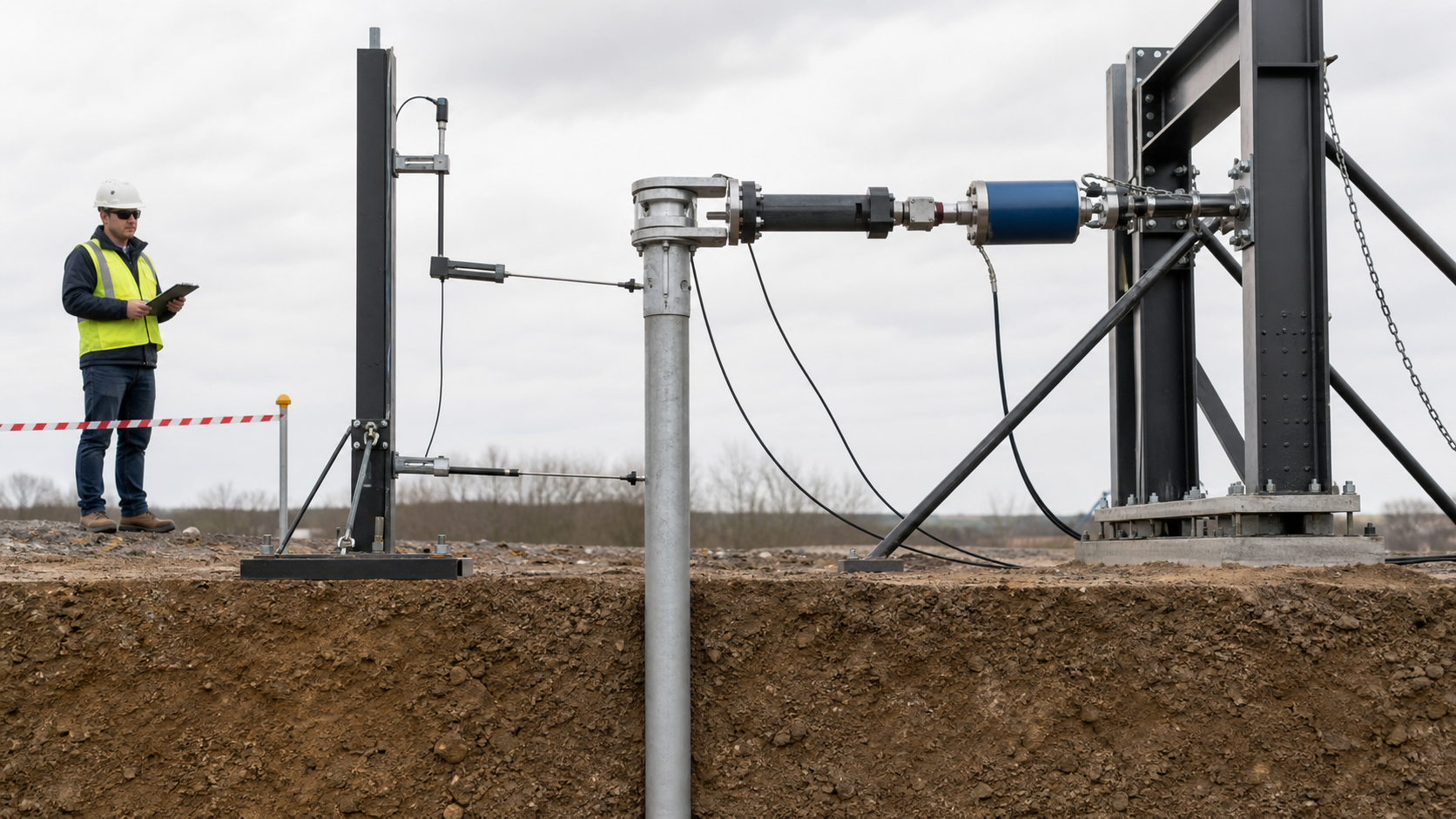
Read the Editorial PolicyA ground screw lateral load test produces a relationship between measured horizontal load and movement for one installed element, one direction, one loading height and one set of ground conditions. It does not produce a context-free capacity. A clean curve can still be unusable if the ground line is undefined, the reaction system influences the reference, the load is applied above the intended connection, or the acceptance rule appears only after the result is known.
This guide begins after the project has selected the test objective and location. It shows how to identify the tested system, align the horizontal load path, measure displacement independently, read the load–movement evidence and separate a project decision from the raw data. The applicable edition and any owner or jurisdictional additions must be confirmed for the project. A lateral load value without its direction, loading height, movement reference and acceptance basis is an incomplete result.
1. Define what the lateral test must decide
A design-stage test may investigate load–movement behavior, calibrate a model or reduce uncertainty in near-surface soil response. A construction verification test may check whether the installed configuration meets a defined proof requirement. A research test may need internal instrumentation to derive bending and soil-reaction relationships. These purposes require different instrumentation, loading extent and interpretation. Name the purpose before selecting the apparatus.
ASTM D3966/D3966M-25 provides a current route for static lateral testing of deep foundation elements and states that project plans or specifications may add requirements. Its public scope also assigns interpretation to the foundation engineer. The test plan should therefore identify the governing documents, required procedure, design or proof objective, planned outputs, stop rules and person authorized to accept deviations before field work begins.
See the current public scope and significance statements for ASTM D3966/D3966M-25. Compliance with one test method does not by itself resolve every owner, code, product-evaluation or contractual requirement.
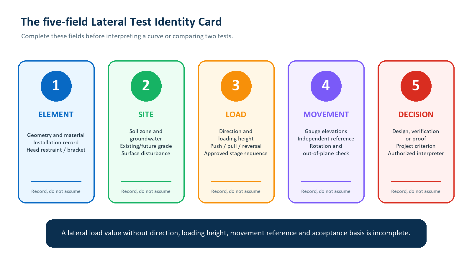
2. Build the five-field Lateral Test Identity Card
Use one identity card for every tested element and direction. The Element field fixes shaft and helix geometry, material, coupling or bracket, installation depth, installation record and intended head restraint. The Site field fixes the test zone, soil and groundwater description, existing and future grade, drainage, excavation, fill and surface disturbance. These two fields determine whether the test is representative of the production condition the project wants to evaluate.
The Load field states direction, loading height, push/pull/reversal mode, head condition and approved sequence. The Movement field states each measurement elevation, instrument, independent reference, rotation method and out-of-plane check. The Decision field states the purpose, project-specific acceptance criterion, authorized interpreter and permitted production scope. If one field changes, the project should decide whether the comparison remains valid.
3. Freeze direction and head condition
Define lateral direction in project coordinates, not as 'left' or 'right' in a photograph. For solar mounting, useful references may include row-longitudinal, row-transverse, upslope/downhill and the principal axes of a post or bracket. An asymmetric shaft, coupling, bracket or connection may respond differently when load direction changes. ICC-ES AC358 requires separate specimens in the lateral directions for which evaluation is sought when the bracket or shaft with coupling is not symmetric; that is an evaluation context, not a universal project test count.
| Identity item | What to record | Misinterpretation prevented |
|---|---|---|
| Direction | Project axis, sign, push/pull mode and relation to slope or row | Comparing opposite or non-equivalent soil/connection directions |
| Head condition | Free, fixed or connection-specific restraint and how it is reproduced | Applying free-head movement to a fixed-head production connection |
| Load contact | Bearing, saddle, pin/swivel and alignment through the intended point | Unrecorded eccentricity, torsion or local damage |
| Out-of-plane check | Secondary gauge, survey point or other approved observation | Treating twist or frame slip as pure lateral movement |
4. Record loading height and the ground line
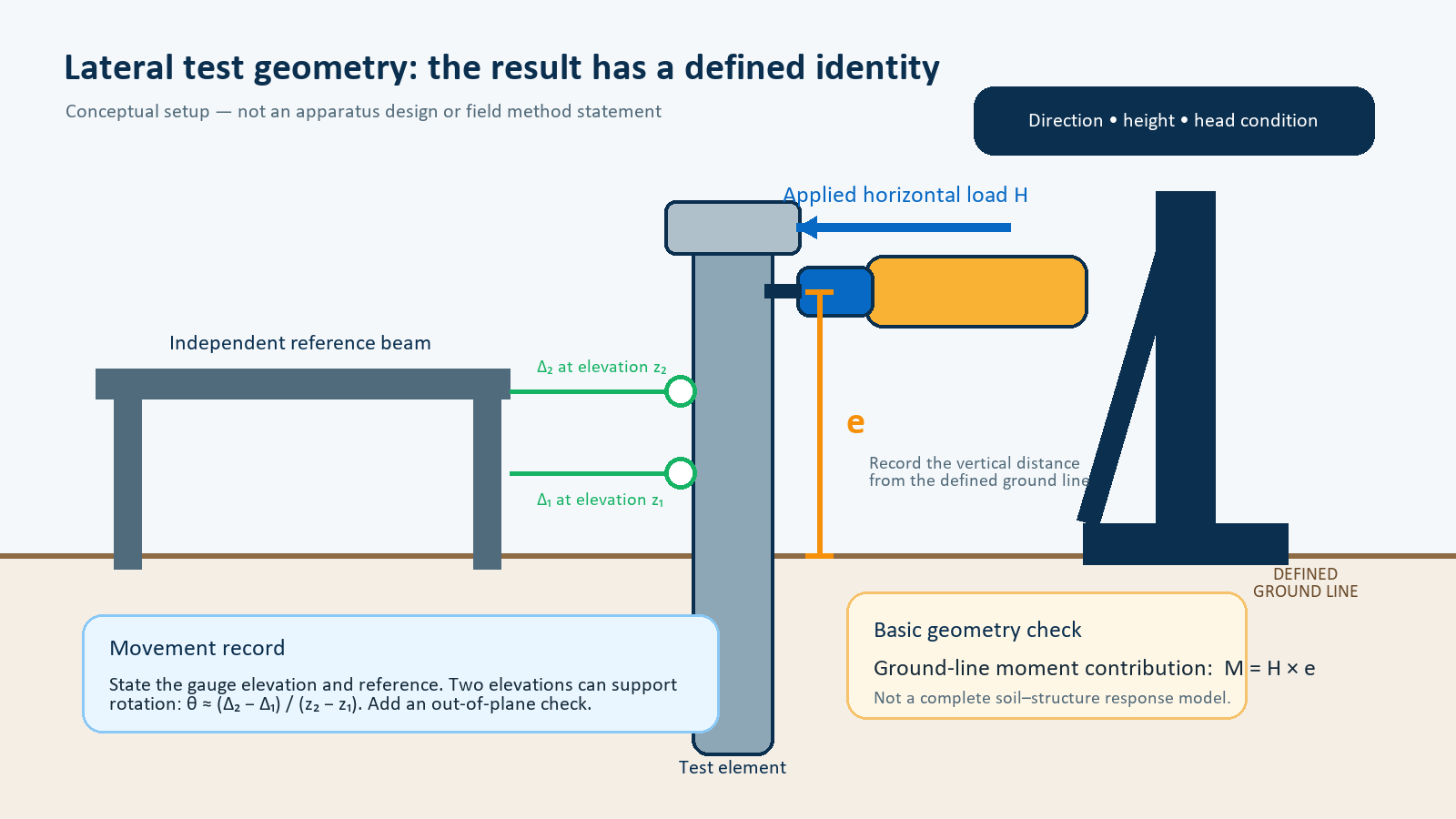
A horizontal force H applied a perpendicular distance e above a defined ground line adds a basic ground-line moment contribution M = H × e. This mechanics relationship explains why two tests at the same horizontal force can impose different head demands when their loading heights differ. It is not a complete prediction of internal bending moment, because soil–structure interaction, head restraint, connection stiffness, element geometry and axial load may change the response.
Measure the loading elevation and the movement-gauge elevations from one surveyed datum. Photograph and describe the ground line, any exposed shaft, local excavation, backfill, crust, mat or surface preparation. ASTM D3966/D3966M-25 identifies loading height, near-surface subgrade condition, future grade or groundwater, scour or excavation and structural sensitivity as factors relevant to interpretation. Do not replace those records with a close-up photograph that has no scale or datum.
5. Confirm the ground and installed element state
Lateral resistance is sensitive to the material close to ground level, where grading, traffic, trenching, backfill, wetting or excavation can change the response. Record the relevant boring, CPT, test pit or other investigation reference; interpreted layer boundaries; groundwater observations; recent weather; surface condition; and any difference between the test state and the final works. A test in firm, undisturbed ground should not be transferred silently to a production zone with loose fill or future excavation.
Record the ground screw product identifier, shaft and helix geometry, couplings, coating, installation date, equipment and tooling, depth, inclination, installation observations and the approved torque/depth record where applicable. Installation torque is an installation input; it is not a lateral-capacity result. If production installation means or element geometry changes, the foundation engineer should evaluate whether the test remains representative.
FHWA's GEC 9 lateral foundation manual notes that installation means and methods, subsurface variability, grade conditions, free- versus fixed-head behavior and single-element versus group behavior can limit how test results are applied.
6. Engineer the reaction system and horizontal load path
The reaction system, loaded members, supports and connections require an engineer-approved design for the anticipated maximum load, travel and movement. A push arrangement may jack against a reaction pile or frame; a pull arrangement may use ties, cables or other approved components. The system must introduce the intended horizontal load without uncontrolled eccentricity, rotation, torsion or local damage at the test head. Components under load require an exclusion zone and a project safety method.
Use a calibrated load cell in the load path as the primary force measurement when required by the approved method. A calibrated jack-pressure gauge can provide a useful backup, but jack pressure alone does not necessarily resolve friction, orientation or system losses. The load cell, readout, jack and connections must have adequate range, resolution, travel and current calibration for the planned test. NIST explains that a transducer calibrated with a particular readout is valid as that calibrated system.
For load-path, reaction, instrument-range and safety context, consult FHWA GEC 9 Chapter 12 and the NIST force-transducer calibration overview. These sources do not approve a project-specific apparatus.
7. Make the movement reference independent
A displacement gauge measures the relative movement between its contact point and its support. If the support moves with the reaction system, disturbed ground or test element, the recorded value is not the intended ground-screw movement. Place reference-beam supports outside the anticipated influence of the test and reaction systems, using the approved standard and engineer's assessment rather than a copied generic distance. Verify the support condition and zero reading before loading.
The reference beam should be sufficiently rigid and protected from direct solar heating, wind, frost, traffic and accidental contact. FHWA recommends attention to thermal effects and a robust reference. Record ambient conditions and periodic reference checks. An apparently smooth curve cannot prove that the beam remained stable; the field record must demonstrate independence.
8. Match instrumentation to the required output
| Required output | Typical measurement set | Boundary |
|---|---|---|
| Proof load and head movement | Calibrated load cell; displacement at a defined elevation; time; field observations | Supports the named proof criterion only |
| Head rotation | Two horizontal movement measurements at known vertical separation, or an approved tilt measurement | Requires stable reference and geometry |
| Out-of-plane behavior | Secondary-axis gauge or survey observation | Checks twist, slip or misalignment |
| Deflected shape | Inclinometer, in-place array or another approved depth-dependent system | Needs baseline, orientation and fixed reference |
| Moment / p-y interpretation | Specialist internal strain or curvature instrumentation plus analysis | Cannot be derived reliably from one head gauge alone |
FHWA GEC 9 lists external instruments such as LVDTs, potentiometers, dial gauges, tiltmeters and calibrated load cells, and internal systems such as strain gauges and inclinometers. Two gauges at different elevations can support a head-rotation estimate when their separation is known. If the objective is only a project proof check, advanced instrumentation may not be necessary; if the objective is model calibration, head movement alone is usually insufficient.
Testing competence and calibration scope also matter. ASTM D3740-23 provides criteria for evaluating soil/rock testing and inspection agencies, while ISO/IEC 17025:2017 addresses testing and calibration laboratory competence. Review the actual accredited scope; an accreditation logo alone does not prove competence for every field activity.
9. Run the approved sequence as synchronized data
Do not invent load increments or hold times in the field. Follow the approved procedure and record target load, actual measured load, elapsed time and each movement channel together. Capture readings at the specified times, including any hold, unload, reload or reversal stage. Record adjustments, seating operations, pauses and observable ground, connection or apparatus behavior in the same timeline.
| Stage record | Minimum synchronized content |
|---|---|
| Identity | Test ID, direction, date/time, operator and approved procedure/revision |
| Load | Target, actual load-cell value, backup value where used and elapsed hold time |
| Movement | Each channel, gauge elevation, zero/reference check and reading time |
| Condition | Temperature/weather, ground observation, head/reaction behavior and photographs |
| Control | Stop, deviation, equipment change, authorized instruction and disposition |
Stop or pause under the approved rules when load cannot be maintained, movement increases unexpectedly, a gauge reaches travel, the reference moves, the load path misaligns, a connection slips, an instrument fails, or the apparatus shows distress. A stopped test is not automatically a failed ground screw. First classify whether the event is element response, apparatus response, measurement loss or an approved safety stop.
10. Interpret the load–movement evidence
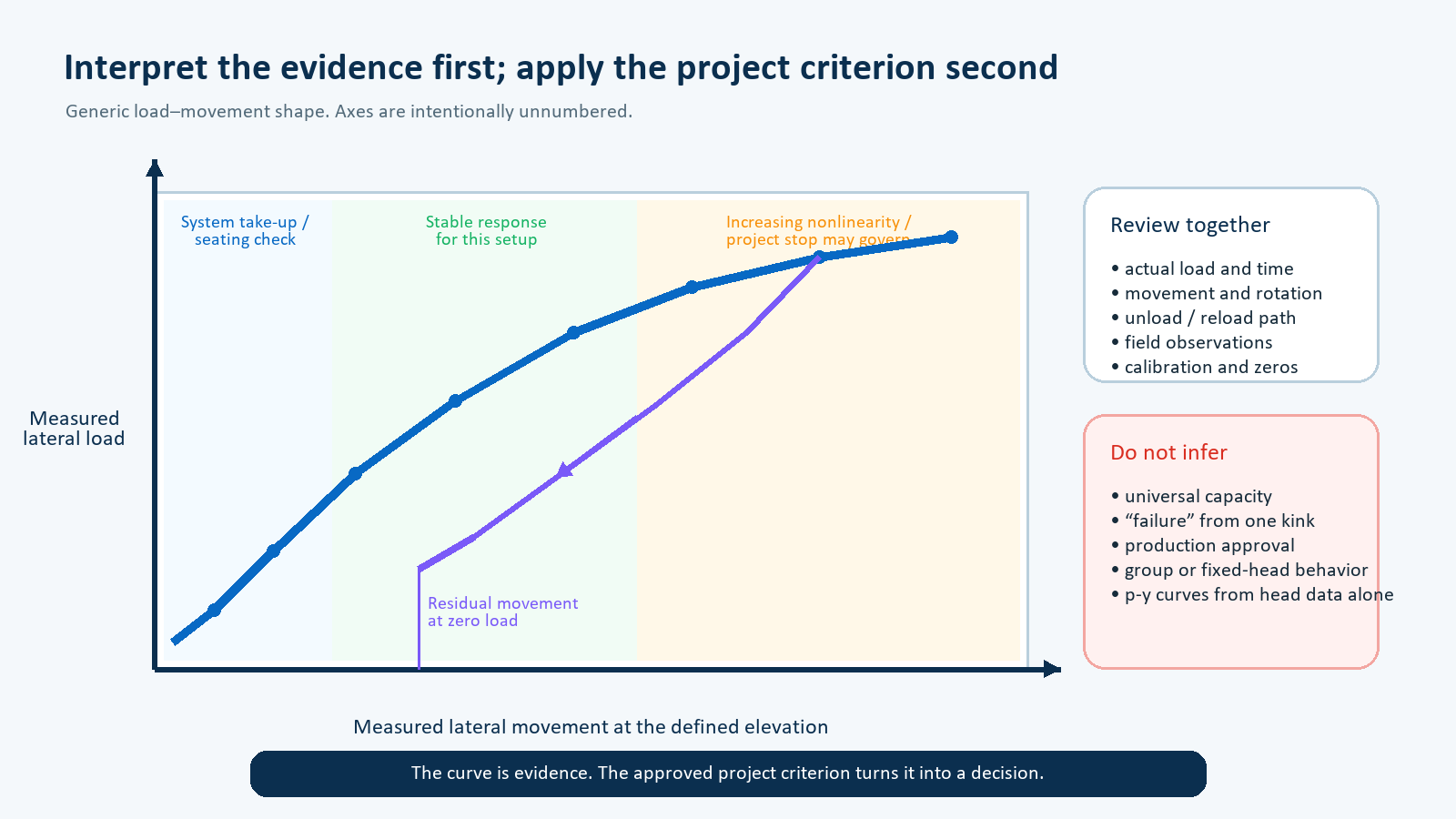
Begin with data validity: calibration, zeros, reference checks, synchronized timestamps, actual load, gauge range and field observations. Then examine the curve shape. Early movement may include system take-up or seating. A later range may show a repeatable, approximately stable relationship for that setup. Increasing nonlinearity may be important, but a single kink does not by itself identify a universal failure load. Check whether it coincides with a hold, reload, gauge change, ground cracking, connection slip or another recorded event.
Review unloading and reloading as well as the loading branch. Residual movement at zero load, a change in reloading slope or progressive movement during a hold may inform the project decision, but none has one universal meaning. If internal instrumentation was used, specialist analysis may derive deflected shape, bending moment or p-y relationships; numerical smoothing and boundary conditions must be documented. Do not derive those outputs from head movement alone.
11. Apply the project-specific acceptance criterion
Acceptance should be written before testing and tied to the test purpose. It may include movement at a service or proof load, maximum test load, residual movement, movement rate during a hold, structural limits, apparatus validity and reporting completeness. State the evaluation point and elevation. If different criteria control serviceability, geotechnical resistance, shaft or connection strength, keep those checks separate rather than collapsing them into one number.
The 2024 International Building Code and ICC-ES AC358 include a route based on one-half of the load associated with 25 mm (1 in) lateral movement in their stated contexts. That value is not a universal ground screw acceptance limit and may not address a project's stricter serviceability requirement, different jurisdiction, head condition or product-evaluation scope. Never import it into an international specification without confirming the adopted code, exact clause, evaluation report and project documents.
Review the applicable context in 2024 IBC Chapter 18 and ICC-ES AC358 (24). The foundation engineer should document why the selected criterion is suitable for the structure and tested configuration.
12. Separate valid/pass, valid/fail and invalid/inconclusive
| Classification | Meaning | Controlled next step |
|---|---|---|
| Valid / pass | Approved method and identity are intact; result satisfies the named criterion | Release only the stated zone, configuration and decision scope |
| Valid / fail | Test is valid but the named criterion is not satisfied | Engineer reviews design, element, installation, ground or test scope |
| Invalid / inconclusive | Load, movement reference, apparatus, identity or procedure cannot support the decision | Do not convert the result into a capacity; determine corrective action or retest |
| Valid / limited | Data are usable for a narrower purpose than originally planned | State the limitation and obtain authorized acceptance of the reduced scope |
This classification prevents an equipment fault from being blamed on the foundation and prevents a valid unfavorable result from being dismissed as 'bad data.' The report should identify the evidence for the classification, the authorized disposition and whether production work is held, changed or released. A successful single-element, single-direction test does not automatically validate groups, other soil zones, different installation methods or different head connections.
13. Issue an auditable data and interpretation package
The factual package should include project and test objectives; site and subsurface context; element drawings and as-installed record; ground line and loading geometry; reaction and reference-system drawings; apparatus calculations/approvals; instrument list, serial numbers and calibrations; approved procedure; synchronized raw data; photographs; weather; deviations; and signed field records. Preserve the original units and avoid silently mixing SI and inch-pound values.
The interpretive package should state data corrections, plotting method, acceptance criterion, comparison point, calculation assumptions, engineer's classification, applicability to production and limitations. FHWA GEC 9 recommends that lateral-test reporting cover the site, foundation construction, setup, procedure, instrumentation, calibration, numerical data, plots, interpretation and limitations. Separating factual data from interpretation can make later review and reuse more controlled.
FHWA's public Route 351 lateral-load test example illustrates the combination of calibrated load measurement, an isolated reference beam, head displacement and depth-dependent inclinometer observations. It is a case study, not a ground-screw acceptance template.
14. What to send East Baoyu
For an engineering review, send the project location, structural reactions and coordinate directions; site layout and grading; geotechnical information; groundwater and drainage notes; proposed ground-screw geometry and connection; installation method; design and proof objectives; governing standard or code; planned loading height; head condition; acceptance criterion; and available test drawings or records. Identify which inputs are preliminary and which are approved.
If a test has already been performed, include the complete identity card, raw synchronized readings, calibration records, ground and installation record, setup photographs, measurement elevations, deviations and the engineer's interpretation. Do not send confidential or export-controlled information through an unapproved channel. East Baoyu can review the supply and engineering-input route, but this article does not promise a test service, capacity, approval, price or schedule.
Use the East Baoyu Screw Piles, Evidence Center and Contact pages to frame the request and confirm the relevant engineering and commercial route.
Request an engineering review
Send the available loads, directions, loading height, ground model, element geometry, installation record and project acceptance basis. East Baoyu can identify missing inputs and discuss the next supply or engineering-review step without treating an incomplete curve as a product-capacity claim.

Open WhatsApp: +86 130 1228 3281
| Contact | Official detail |
|---|---|
| info@eastbaoyu.com | |
| Phone | +86 22 28352066 |
| +86 130 1228 3281 | |
| Website | https://eastbaoyu.com/contact/ |
Email the project inputs: info@eastbaoyu.com
Frequently asked questions
What does a ground screw lateral load test measure?
It measures the relationship between applied horizontal load and movement for the tested element, direction, loading height, head condition and ground state. The foundation engineer determines how that evidence applies to the project.
At what height should the lateral load be applied?
At the height defined by the approved project test plan. The height must represent the decision being made and must be recorded from a defined ground line or datum. There is no universal height for every connection.
Is 25 mm of lateral movement a universal acceptance limit?
No. The 25 mm / 1 in route appears in specific IBC and ICC-ES contexts. A project may have a different code, serviceability limit, proof criterion, connection condition or owner requirement.
How many load directions should be tested?
The approved program should select directions from structural demand, soil or slope conditions, element and connection symmetry, risk and applicable evaluation requirements. One direction does not automatically represent every axis or reversal.
Why must the displacement reference be independent?
Because a gauge records relative movement. If its support moves with the reaction system or influenced ground, the reading can include reference movement and no longer represent the intended ground-screw movement.
Can one successful test approve all production ground screws?
Not automatically. The project must define the represented soil zone, element geometry, installation method, direction, head condition and acceptance scope. Group effects and site variability may require separate evaluation.
Related East Baoyu resources
Ground Screw Piles | Engineering Articles
Evidence Center | Contact East Baoyu
Ground Screw Selection from Site Investigation | Installation Torque and Ground Screw Capacity
Screw Piles vs. Concrete Foundations | Research & Methods
References and scope notes
Official public sources were checked on 28 July 2026 and are paraphrased within their public scope. Licensed standards and paywalled text were not reproduced. Confirm the applicable edition, amendments, adopted code, owner requirements, geotechnical report, product evaluation, project specification and engineer-approved method. This guide is not an apparatus design, method statement, safety plan, test report, capacity certification, code approval or commercial commitment. Ground screws and helical pile systems vary; the exact system and jurisdiction control.
ASTM D3966/D3966M-25 public scope | FHWA GEC 9 — Laterally Loaded Deep Foundations
FHWA GEC 12 Volume II — Driven Pile Foundations | ICC-ES AC358 (24) — Helical Pile Systems and Devices
2024 IBC Chapter 18 | USACE EM 1110-2-2906 — Design of Pile Foundations
ASTM D3740-23 public scope | ISO/IEC 17025:2017
NIST Calibration of Force Transducers | FHWA-HRT-04-043 lateral load test case study
References, disclosure and change record
References and further verification
- https://store.astm.org/d3966_d3966m-25.html
- https://www.fhwa.dot.gov/engineering/geotech/pubs/hif18031.pdf
- https://www.nist.gov/programs-projects/calibration-force-transducers
- https://store.astm.org/d3740-23.html
- https://www.iso.org/standard/66912.html
- https://codes.iccsafe.org/content/IBC2024P1/chapter-18-soils-and-foundations
- https://icc-es.org/evaluation-report-listing/ac358/
- https://www.fhwa.dot.gov/publications/research/infrastructure/structures/04043/04043.pdf
- https://eastbaoyu.com/screw-piles/
- https://eastbaoyu.com/evidence-center/
- https://eastbaoyu.com/contact/
- https://wa.me/8613012283281
- https://wa.me/8613012283281?text=Hello%20East%20Baoyu%2C%20I%20would%20like%20to%20discuss%20a%20ground%20screw%20lateral%20load%20test%20setup%20and%20project%20inputs.
- https://eastbaoyu.com/articles/
- https://eastbaoyu.com/ground-screw-selection-from-site-investigation/
- https://eastbaoyu.com/installation-torque-and-ground-screw-capacity/
- https://eastbaoyu.com/screw-piles-vs-concrete-foundations/
- https://eastbaoyu.com/research-methods/
- https://www.fhwa.dot.gov/engineering/geotech/pubs/gec12/nhi16009_v2.pdf
- https://www.publications.usace.army.mil/portals/76/publications/engineermanuals/em_1110-2-2906.pdf
Disclosure: East Baoyu manufactures and supplies products discussed on this website. Structured drafting tools may assist research and editing, but technical claims, project inputs and release decisions require qualified review under the applicable project responsibilities.
Version 1.0: Initial scheduled publication in the East Baoyu engineering knowledge-base batch.
View the public Content Change Log · Corrections: info@baolaipipes.com