

Authorship, review and evidence boundary
- Technical review
- East Baoyu Engineering Editorial Team
- Reviewed
- 2026-08-24
- Scope
- General engineering and procurement guidance. This article is not a project-specific design, capacity statement, certificate, warranty, code interpretation or contract requirement.
Evidence basis: Official and public references identified in the article. Project values and release decisions require qualified review under the applicable project responsibilities.
Read the Editorial PolicyA ground screw load capacity value is usable only when its scope is explicit: load direction, design basis, pile and head configuration, ground zone, movement criterion, verification route and approving authority. A catalog number, isolated test result or installation-torque reading cannot be transferred to a project by itself. The foundation decision must connect structural demand to ground resistance, every pile component and interface, serviceability, durability, installation evidence and the adopted code. This guide gives foundation engineers and EPC reviewers a capacity-claim decoder, load-path map, governing-limit register and evidence ladder. It does not publish a universal capacity, replace a project calculation, interpret a test for a real site or certify an East Baoyu product for a particular load.
Decode the capacity statement before comparing numbers
“Capacity” can refer to different quantities. It may describe compression, uplift, lateral resistance or a combined action. It may be an ultimate test result, an allowable working value, a design resistance, a movement-limited value or a component strength. These terms are not interchangeable, and the applicable factors and combinations come from the adopted design basis.
Use the following original East Baoyu decoder before a value enters a comparison, foundation schedule or quotation review.
| Capacity label | Question that must be answered | If missing |
|---|---|---|
| Value and units | What is the stated value, unit system and rounding basis? | The number cannot be checked or compared. |
| Load direction | Compression, axial tension/uplift, lateral, moment or a defined combination? | The demand and verification route are unknown. |
| Design level | Ultimate result, characteristic resistance, design resistance, allowable/working load or another defined level? | Factors may be applied twice, omitted or mixed. |
| Reference point | At which pile/head level, direction and connection condition is demand applied? | Eccentricity and interface effects may be hidden. |
| Product scope | Which shaft, helix, coupling, extension, head, fasteners, material and manufacturing revision? | A different configuration may control. |
| Ground scope | Which site, zone, strata, groundwater and installation condition? | Site applicability is unproved. |
| Performance limit | Which movement, rotation, settlement or other criterion accompanies the value? | Strength may be acceptable while performance is not. |
| Evidence and authority | Which calculation, test, correlation or evaluation supports the statement, and who approved it for what decision? | Treat it as screening information only. |
The European Commission's Joint Research Centre describes Eurocode 7 as a geotechnical-design framework used with the basis of design and verification for safety and serviceability. Its current page also points to separate serviceability-limit-state work under the second-generation Eurocodes (JRC — Eurocode 7). That is one regional framework, not the default code for every project, but it illustrates a general control: a strength number does not close a serviceability decision.
The East Baoyu screw-pile page therefore treats catalog dimensions and website examples as selection inputs, not an approved pile schedule or project capacity statement.
Trace each action through the complete foundation path
Start with reactions from the supported structure, not with a pile catalog. The load schedule should identify direction, sign convention, combinations, design level, reference elevation, eccentricity, temporary conditions and serviceability limits. It should also show whether the head is intended to transfer axial load, shear, moment or a combination.
This is a logic map, not a calculation method. The appointed designer chooses the adopted model and determines how compression, uplift, lateral action and moment pass through the connection and pile. A favourable ground-resistance estimate cannot validate an undersized coupling. A strong shaft cannot correct an incompatible head detail. A satisfactory single-pile result may not establish group behaviour, global stability or the supported structure's movement tolerance.
Freeze the interface before using a capacity claim. Head fixity, bolt pattern, lever arm, pile inclination, final level and construction tolerance can change the forces and deformation that individual components experience. If the structure or connection revision changes, reopen the capacity basis rather than carrying the old number forward.
Tie ground resistance to a defined zone and pile configuration
Ground screw load capacity cannot be selected from a soil name such as “clay,” “sand” or “rocky ground.” The capacity model needs a project ground profile and a defined pile configuration. Relevant inputs may include strata and variability, strength and stiffness parameters, groundwater, fill, weak layers, obstructions, weathering, cavities, slope or scour conditions, and the coverage of the investigation. The project geotechnical authority decides which inputs and methods apply.
The pile must be described with equal precision: shaft type and dimensions, helix or ground-engaging geometry, length and extensions, coupling details, material, head condition and installation criteria. A longer element or larger helix does not automatically justify a higher project value; it can change the structural limit, installation route, ground mechanism and evidence needed.
ICC-ES AC358, where the ICC-ES evaluation route for helical pile systems and devices is adopted, separates soil capacity from capacities associated with the shaft, couplings and helix/device elements. It also makes soil capacity site-specific and recognizes only documented torque correlations within its defined conditions (ICC-ES AC358). AC358 is not a universal specification for every ground screw, and this article does not imply that East Baoyu holds a particular evaluation report. Its useful lesson is the separation of evidence: ground resistance and product-component resistance must both be established.
Use the site-investigation selection guide to define zones and missing ground decisions. A trial or load test at one point should not erase unresolved variability elsewhere.
Find the governing structural and interface limit
A capacity statement is only as strong as its least-verified applicable link. The exact checks depend on the design method and product, but the review register should expose every possible owner instead of allowing one headline value to stand for the system.
| Governing item | Questions for the project review | Evidence owner/output |
|---|---|---|
| Head and supported-system connection | Are bearing, bolts, welds, plate behaviour, local distortion, eccentricity and moment transfer defined? | approved interface drawing and structural check |
| Shaft | Are compression, tension, bending, shear, buckling and combined actions checked where applicable? | structural calculation tied to material and geometry |
| Extensions and couplings | Does each connection transfer the required actions through the installed configuration and tolerances? | connection detail, qualification/evaluation and design check |
| Helix or ground-engaging element | Are plate/device strength, deformation and attachment to the shaft verified? | product calculation, evaluation or test within scope |
| Soil or rock | Does the adopted model match the ground zone, pile geometry, installation condition and load direction? | geotechnical calculation and ground-model reference |
| Group and global system | Do spacing, interaction, pile-cap or frame behaviour and overall stability change the single-element result? | group/global foundation model and layout revision |
| Serviceability and supported structure | Are movement, rotation and differential effects within the structure's approved limits? | load–movement assessment and interface acceptance |
Do not add unrelated component capacities or choose the largest result. The adopted design process identifies how each resistance and action is combined and which limit governs. If one row remains unverified, the capacity statement must either remain Pending or be restricted to a decision that does not depend on that row.
Keep serviceability, time and durability inside the scope
Foundation failure is not the only unacceptable outcome. Settlement, uplift movement, lateral displacement, rotation or differential response can control the supported structure before a strength limit is reached. The acceptable movement depends on the structure, connection, equipment and project criteria; this guide cannot supply a generic threshold.
Time and loading history may also matter. Repeated, cyclic, sustained or construction-stage actions can differ from a single monotonic test. Changes in grade, groundwater, scour, adjacent work, drainage or supported-system configuration can alter the conditions represented by an earlier calculation or test. The responsible designer should state which effects are included, excluded or assigned to later verification.
Durability is another condition on the capacity statement. The section, coating, sacrificial allowance, connection detailing, soil/atmospheric exposure, design life, damage and inspection strategy need an approved basis. A material or coating label alone does not prove retained capacity through the project life. Use the related corrosion-design guide for that workflow.
The capacity-basis record should therefore state both the design condition and its validity boundary: product revision, ground zone, installation method, service stage, exposure, assumed maintenance and any event that reopens review.
Match tests and installation data to the capacity claim
Evidence should be selected for the question being decided. A catalog supports early screening. A calculation checks a stated model and inputs. A test measures the response of a defined element under a defined method. Installation data show how production work matched approved controls. None automatically substitutes for the others.
| Evidence level | What it can support | What it cannot establish alone |
|---|---|---|
| Catalog or generic data | product-family screening and questions for an inquiry | site capacity, final pile schedule or approval |
| Project calculation | a resistance/movement check for the stated loads, model, configuration and ground inputs | conditions outside its assumptions or unverified construction |
| Product evaluation or qualification | defined component/system properties within the report's scope | a different product, site, code, installation or connection |
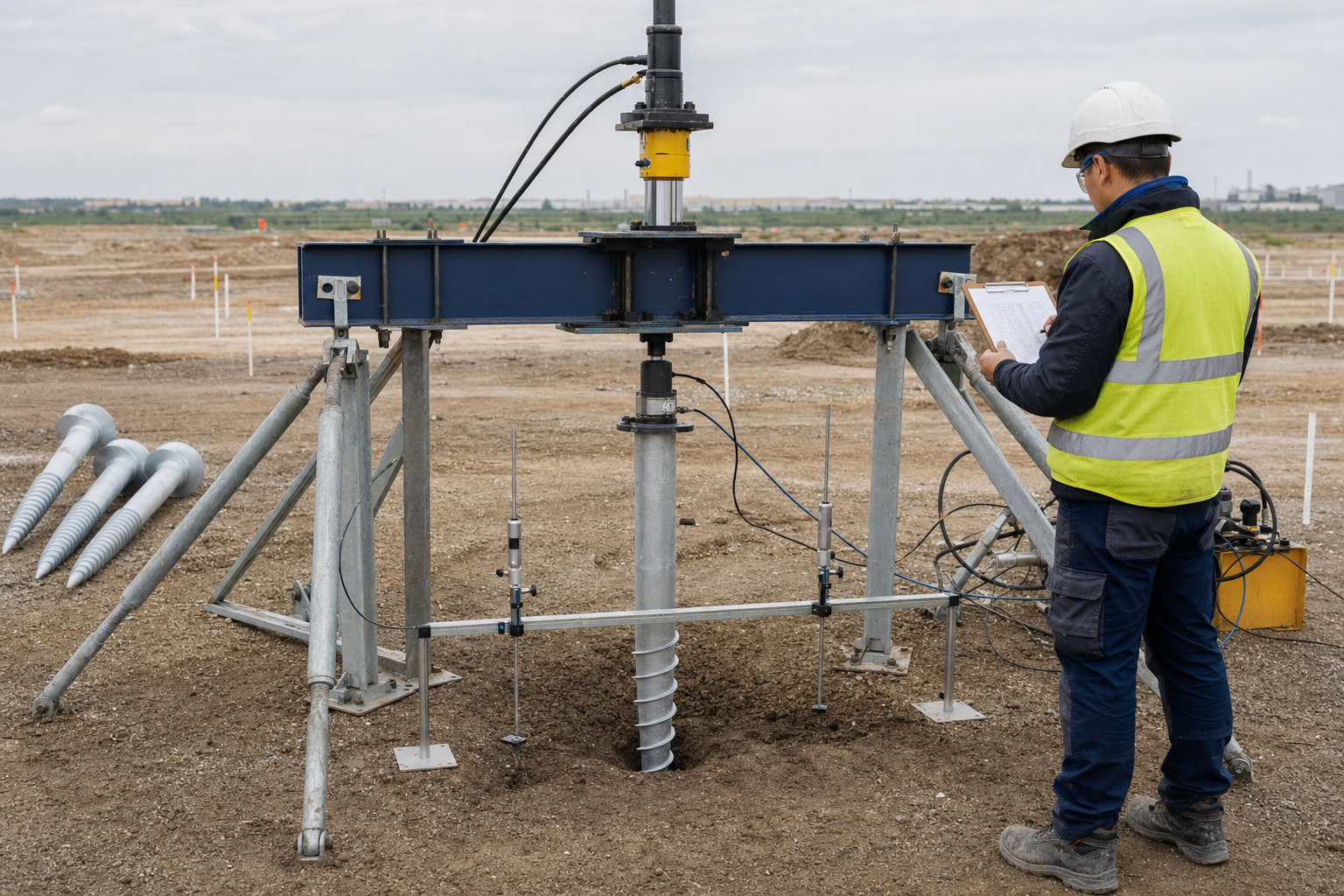
| Direction-specific load test | load–movement evidence for the tested element, setup, direction, procedure and conditions | every untested zone, configuration, load direction or long-term system response |
| Installation record or torque data | identity, depth, equipment, process observations and production conformity | capacity without an approved relationship and applicability boundary |
| Approved capacity-basis record | use of the assembled evidence for a named project decision | any purpose, revision or location outside its release scope |
ASTM D1143/D1143M-26 addresses static axial compression testing. Its official scope notes that applying a result to untested elements depends on comparable subsurface conditions, element type, geometry and installation method, and that engineering procedures and interpretation remain project responsibilities (ASTM D1143/D1143M-26). ASTM D3689/D3689M-25 covers static axial tensile testing (ASTM D3689/D3689M-25); ASTM D3966/D3966M-25 covers static lateral testing and identifies conditions that affect interpretation (ASTM D3966/D3966M-25). These standards do not create one interchangeable “ground screw capacity” or a universal project test requirement.
Installation torque may support a capacity route only where a documented relationship is approved for the relevant product, equipment, ground and operating limits. The separate guide on installation torque and ground screw capacity owns that correlation workflow. This article uses torque only as one evidence field inside the broader capacity basis.
Release only a bounded capacity basis
Turn the review into a controlled record rather than leaving the capacity inside an email or chart. Give the record an ID and revision, then state the project and location; intended decision; load cases, directions and design level; pile and interface configuration; ground zone and source; calculation/evaluation/test references; serviceability and durability conditions; installation controls; exceptions; approving roles; and expiry or change triggers.
Assign a status that matches the evidence. Screening only may support option development. Preliminary may support a declared comparison while listed inputs remain open. Approved for stated design use belongs only to the designated authority and exact revision. Installation control should identify the observations that keep production inside the approved basis. Superseded prevents an old number from surviving a changed layout, ground model or product.
The final boundary is simple: use a ground screw load capacity only for the pile, interface, ground zone, load direction, design condition and decision named in its approval. No attractive catalog value can close a missing load path. No single test can represent unverified conditions by default. No torque reading can approve capacity without a bounded relationship. Assemble the demand, ground, structural, serviceability, durability and verification evidence; identify the governing limit; and record who releases the value. If one required link is missing, preserve it as an input or Pending decision rather than filling the gap with a generic number.
Related Resources
- Ground Screw Piles
- Ground Screw Design Input Checklist
- Ground Screw Selection from Site Investigation
- How to Plan a Ground Screw Load Test Program
References
- European Commission JRC — Eurocode 7: Geotechnical Design
- ICC-ES — Acceptance Criteria for Helical Pile Systems and Devices, AC358
- ASTM — D1143/D1143M-26, Static Axial Compressive Load
- ASTM — D3689/D3689M-25, Static Axial Tensile Load
- ASTM — D3966/D3966M-25, Static Lateral Load
Next Step: Submit the Capacity-Basis Inputs
Send the controlled load schedule, ground/geotechnical references, pile and head configuration, layout, adopted design basis, serviceability and durability requirements, and available calculation, test and installation records. East Baoyu can identify missing supplier inputs and provide available product, material and interface information within the agreed supply scope. The project's appointed structural and geotechnical professionals remain responsible for the design method, capacity, tests, interpretation, approvals and final release.
Contact East Baoyu or email info@baolaipipes.com.
References, disclosure and change record
References and further verification
- https://eurocodes.jrc.ec.europa.eu/EN-Eurocodes/eurocode-7-geotechnical-design
- https://eastbaoyu.com/screw-piles/
- https://icc-es.org/evaluation-report-listing/ac358/
- https://eastbaoyu.com/ground-screw-selection-from-site-investigation/
- https://eastbaoyu.com/corrosion-design-ground-screws-solar-steel/
- https://store.astm.org/d1143_d1143m-26.html
- https://store.astm.org/d3689_d3689m-25.html
- https://store.astm.org/d3966_d3966m-25.html
- https://eastbaoyu.com/installation-torque-and-ground-screw-capacity/
- https://eastbaoyu.com/ground-screw-design-input-checklist-epc-procurement-teams/
- https://eastbaoyu.com/plan-ground-screw-load-test-program/
- https://eastbaoyu.com/contact/
Disclosure: East Baoyu manufactures and supplies products discussed on this website. Structured drafting tools may assist research and editing, but technical claims, project inputs and release decisions require qualified review under the applicable project responsibilities.
Version 1.0: Scheduled in the East Baoyu 30-article engineering knowledge-base batch on 2026-08-25.
View the public Content Change Log · Corrections: info@baolaipipes.com