

Authorship, review and evidence boundary
- Technical review
- East Baoyu Engineering Editorial Team
- Reviewed
- 2026-07-29
- Scope
- General engineering and procurement guidance. This article is not a project-specific design, capacity statement, certificate, warranty, code interpretation or contract requirement.
Evidence basis: Official and public references identified in the article, together with original editorial diagrams. Project values and release decisions require qualified review under the applicable project responsibilities.
Read the Editorial PolicyA ground screw uplift test can generate a persuasive load-displacement curve and still leave the project unable to use the result. That happens when the test purpose is vague, the element is not representative, the head connection changes the load path, the reaction system interacts with the same ground, the instruments are not traceable or the acceptance rule is written after the result is known. The field team may have followed a recognized method, but the project did not define the decision around it.
This guide explains what an uplift-test specification should close before mobilization. It is written for ground screws and related screw-pile systems, but it does not declare one standard suitable for every product or jurisdiction. ASTM D3689/D3689M-25 and ISO 22477-2:2023 provide current routes for static axial tension testing of deep foundations or piles within their scopes. The contract, adopted code, ground model, responsible engineer and project specification remain controlling.
1. Define the decision before naming the apparatus
State the decision the result must support. An investigation test may explore the load-displacement response of a proposed geometry and installation route. A suitability or pre-production test may assess whether a selected system behaves as expected under representative conditions. A production proof test may check a defined installed element against an agreed criterion. These labels are not interchangeable across every code or contract, so the specification should define the label, the decision owner and the permitted downstream action in plain language.
| Decision field | Question the specification must answer |
|---|---|
| Purpose | What uncertainty or acceptance decision will the test address? |
| Scope | Which product, ground zone, installation route and project stage are covered? |
| Result use | Design interpretation, suitability review, production evidence or another bounded use? |
| Authority | Who approves the method, interprets the result and releases the next action? |
2. Build the eight-clause specification
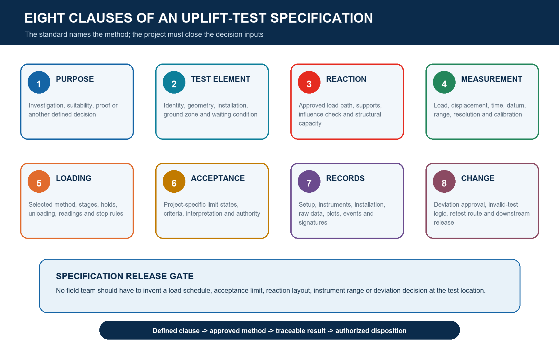
The eight clauses create a specification that can be reviewed before equipment reaches site. Purpose defines the decision. Test Element fixes what is being tested. Reaction controls how the opposite force enters the ground and frame. Measurement makes load, movement and time traceable. Loading selects the procedure and stage logic. Acceptance sets the decision rule. Records preserve the evidence. Change prevents field improvisation from becoming an undocumented new method.
3. Select the governing test basis and method
Name the adopted standard, exact edition, test method and project additions. ASTM D3689/D3689M-25 states that project plans or specifications may add requirements and that the foundation engineer approves deviations, additions or deletions. Its public guidance also notes that different loading procedures can produce different load-displacement curves. ISO 22477-2:2023 addresses maintained-load static tension tests and expressly does not cover cyclic pile load tests. Therefore a specification that merely says 'test to ASTM' or 'test to ISO' leaves material choices unresolved.
If the project needs a quick, maintained, constant-rate, sustained, cyclic or repeated uplift sequence, select the route deliberately and verify that the cited method covers it. Where the project uses helical-pile evaluation evidence such as ICC-ES AC358, distinguish product-evaluation testing from the construction-project test being specified. A report developed for an evaluation route does not automatically replace site-specific design, installation and acceptance requirements.
4. Freeze the test element and installation condition
Identify the tested ground screw as rigorously as a production component. Record the manufacturer and product designation, shaft and helix geometry, steel and coating, couplers, head detail, installed length and inclination, tip elevation, ground zone, installation equipment, rotation and penetration history, torque record, refusal or obstruction events, final head elevation and the time between installation and testing. If the test element is sacrificial, strengthened or specially installed, state how that difference affects interpretation.
| Identity group | Minimum controlled information |
|---|---|
| Product | Designation, drawing revision, shaft, helix, coupler, head, material and coating |
| Location | Coordinates, ground zone, surface level, groundwater observations and nearby works |
| Installation | Date/time, equipment, operator, inclination, depth, torque/rotation record and events |
| Condition | Waiting period, excavation/fill, weather, disturbance, damage and pre-test inspection |
5. Define the uplift connection and axial load path
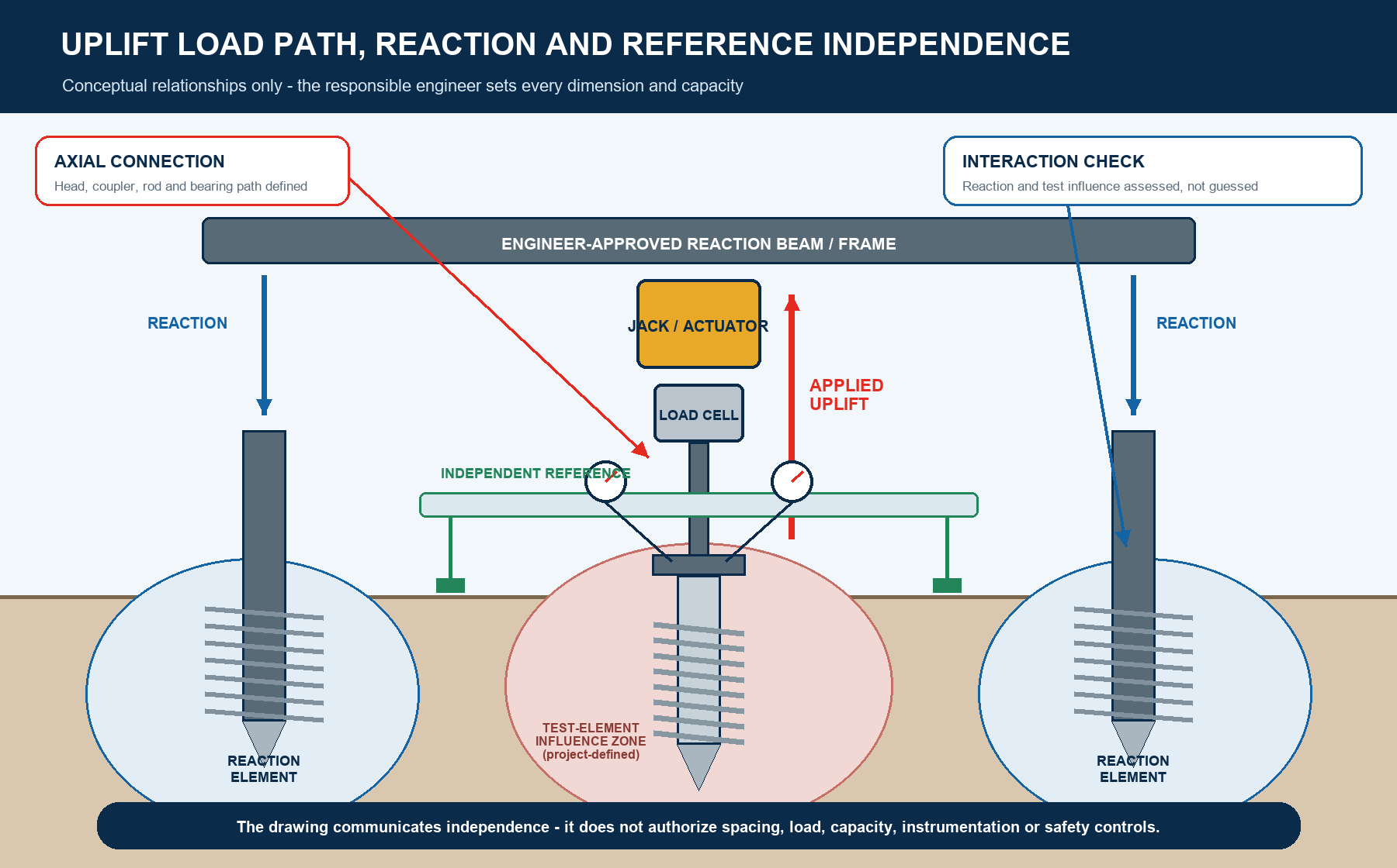
The tensile connection at the head is not a temporary convenience. The specification should define the approved head, coupler, tension rod, clevis or adapter, bearing surfaces, load-cell position and jack or actuator alignment. Check each component for the selected maximum apparatus load and foreseeable eccentricity. Confirm that the test connection does not create a failure mode absent from the production detail unless that condition is intentional and interpreted. Rotation restraint, thread engagement, weld details and any local reinforcement also need a controlled basis.
6. Engineer the reaction system and ground interaction
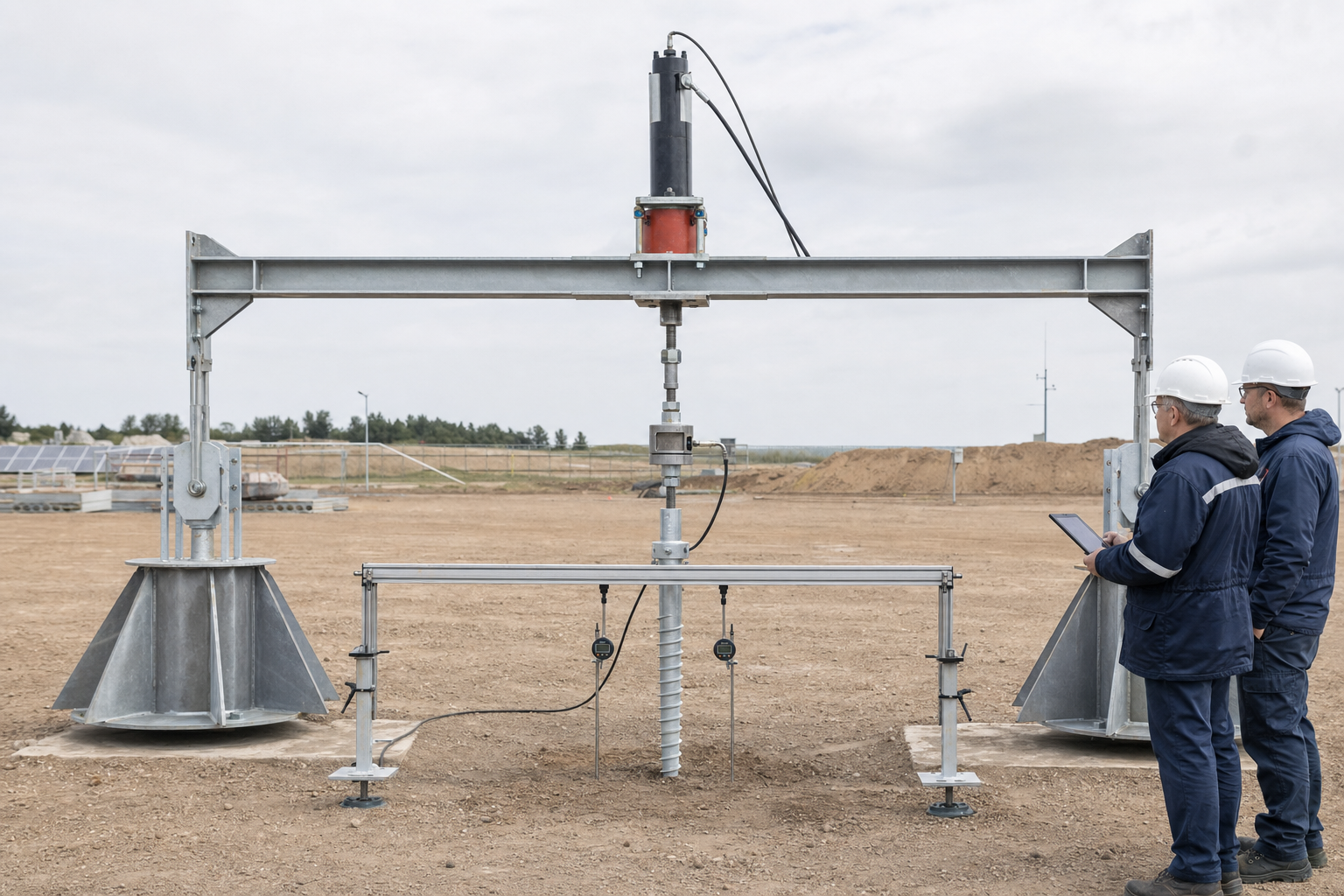
An uplift test pulls the test element upward while the frame transfers opposite reaction forces into separate supports, anchors, kentledge or another approved system. The specification should require a design package for the beam or frame, connections, supports and loaded members; identify the rated capacity and proof or inspection basis; and define how stability, lateral restraint, settlement, rotation and safe exclusion are controlled. ASTM's public scope places design and approval of loading apparatus and loaded members with a qualified engineer.
Spacing should follow a documented ground-interaction assessment, not a copied universal number. Reaction elements may mobilize soil that overlaps the zone influencing the test ground screw, and a surface support may settle or rotate as load increases. Record the foundation geometry, ground profile and assumed influence mechanism used to approve the layout. The specification should also define what movement or instability of the reaction system triggers a pause, redesign or invalid-test review.
7. Keep movement measurement independent and traceable
Define the displacement datum, reference supports, reference beam, device locations, number of measurement points and method for detecting rotation or eccentric movement. Reference supports must be independent of both the reaction frame and test-element movement within the project-approved influence assessment. Specify device range, resolution, expected accuracy, zeroing, reading direction, environmental protection, manual or electronic capture and a stability check before and during loading.
Apply the same discipline to force and time. Name the load cell or pressure-to-force route, its calibrated range, certificate number, validity, traceability, indicator and data logger. ASTM E74-18(2026) and ASTM E4-24 provide force-calibration and verification concepts when adopted by the project; ASTM E2309/E2309M-20 provides comparable displacement-verification concepts for testing machines. These references do not automatically govern every field device, so the specification must state the accepted route and required evidence.
8. Write the load sequence as controlled parameters
A usable schedule defines values and actions, not only a maximum test load. State the preload or seating rule, datum reset, load-control mode, stage targets, tolerance around each target, minimum and extension hold logic, reading times, unload stages, rebound readings, termination criteria and whether repeated or cyclic actions are included. Keep one governing unit system. If both SI and inch-pound values are shown, identify the controlling set rather than mixing rounded conversions.
| Schedule parameter | Project specification entry |
|---|---|
| Basis | Selected method/edition, test purpose, design action and maximum apparatus load |
| Stages | Target loads, control tolerances, loading rate or step rule and sequence owner |
| Holds/readings | Minimum hold, extension condition, synchronized load/movement/time points |
| Unload/rebound | Unload stages, observation period, residual movement and zero checks |
| Stops | Safety, equipment, alignment, movement, ground or data conditions requiring action |
9. Establish acceptance before field mobilization
Acceptance cannot be reconstructed from a curve after testing. Define the required load level, permissible movement at named stages, sustained-movement or creep evaluation, residual movement, structural integrity, observed failure modes, validity conditions and method of interpretation. State whether the test is intended to demonstrate service response, ultimate resistance, production proof or another objective. A limit meaningful for one structure, ground condition and method may be inappropriate for another.
Separate field observation from engineering interpretation and release. The testing team records what happened. A qualified reviewer checks the test's validity and applies the agreed interpretation. The contract-named authority approves the disposition and any effect on design or production. This separation prevents a field label such as 'held the load' from being mistaken for project acceptance. It also allows an unexpected but valid result to be reviewed without changing the criteria retrospectively.
10. Define stop, deviation and invalid-test rules
Write stop rules for unsafe conditions, unexpected frame movement, loss of alignment, leakage, device overload, unstable readings, reference movement, connection distress, ground cracking, sudden displacement, power or logging failure and any project-specific limit. Name who can stop the test and who may authorize restart. A stop protects people and evidence; it is not automatically a failed ground screw.
Classify outcomes before testing: valid and acceptable; valid but outside acceptance; valid and inconclusive for the intended decision; or invalid because the approved method was not achieved. Define notification, preservation of raw data, investigation, engineering review, repair or retest route and whether the element may be reused. No one should change a load stage, hold, device, connection or reaction layout in the field without the approval and revision process stated in the specification.
11. Require synchronized raw data and an auditable report
Every reading row should retain actual load, displacement at each device, elapsed and clock time, target stage, hold status, environmental or site observations, equipment events and operator initials. Preserve original electronic files and manual sheets. Photographs should show the overall setup, load path, reaction supports, reference supports, instrument identities and pre/post-test condition without relying on photographs as a substitute for measurements.
| Report section | Minimum evidence |
|---|---|
| Basis | Specification, standard/edition, approved method, purpose, criteria and authorities |
| Element | Identity, drawings, ground zone, installation record, condition and deviations |
| Apparatus | Layout, design/approval, components, ratings, calibration and inspection records |
| Data | Raw synchronized readings, curves, calculations, observations and original files |
| Disposition | Validity review, interpretation, acceptance result, conditions and approval |
12. Control how one uplift result reaches production
Before applying the result, compare the tested and production elements: product geometry, material and couplers; head connection; installed depth and inclination; ground zone; groundwater and grade; installation equipment and method; torque and penetration history; time effects; nearby construction; and the governing load case. If those conditions vary, limit the result to the defined subset, require additional testing or use another approved engineering route. A successful test is evidence for a bounded population, not a site-wide guarantee.
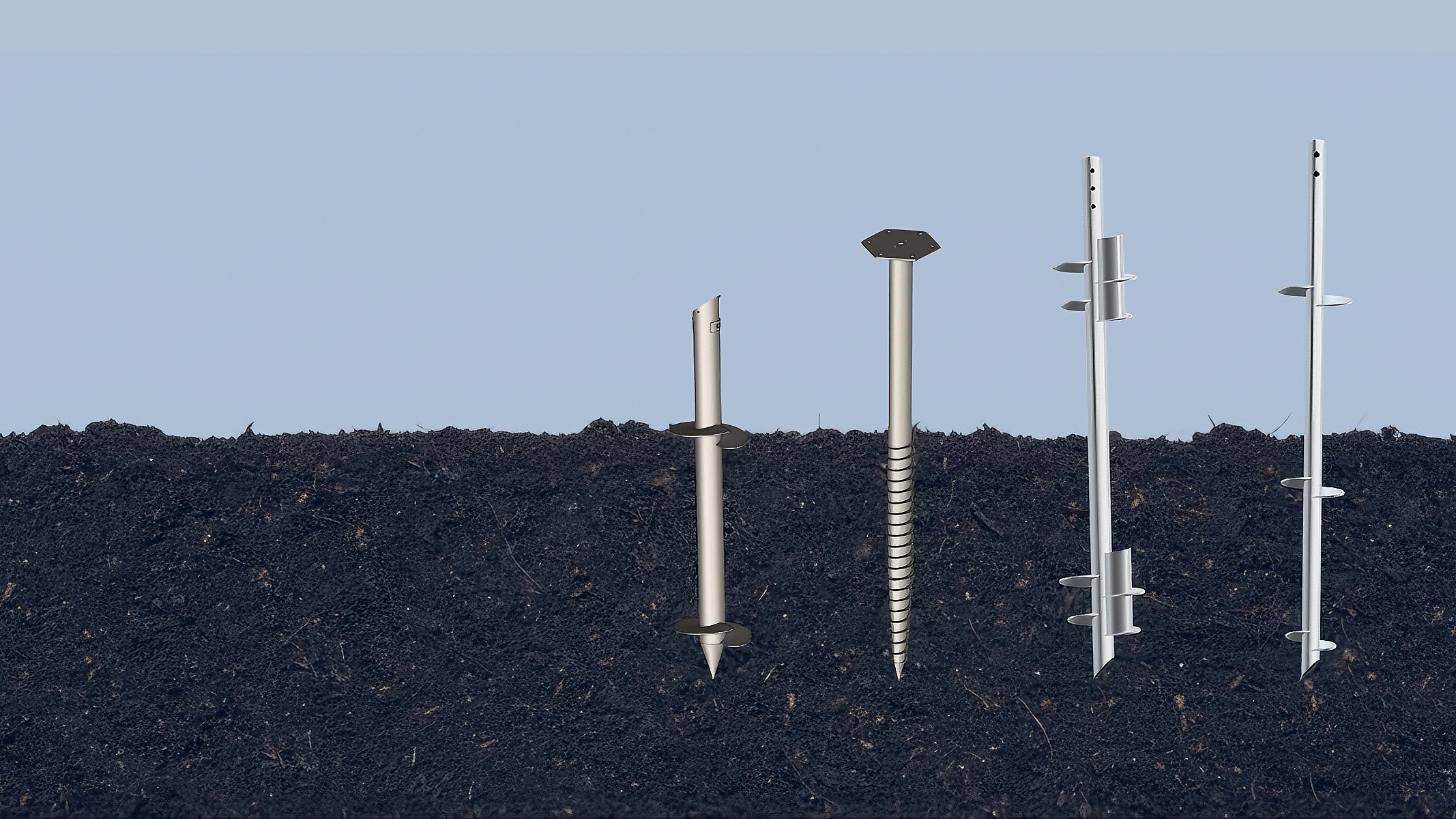
Installation torque may be included as a controlled installation variable, but it does not replace the uplift test or create a universal capacity relationship. A project correlation requires representative products, ground conditions, installation variables, test quality and an approved statistical or engineering interpretation. Keep the test result, torque record and production acceptance route linked without treating them as identical evidence.
13. Release the specification through a final checklist
Purpose, scope, result use and named approval authorities are unambiguous.
Test element, ground zone, installation record and waiting condition are frozen.
Standard, edition, selected method and every project addition are stated.
Uplift connection, reaction design, influence assessment and reference independence are approved.
Force, displacement and time devices have suitable ranges and traceable records.
Loading, readings, unloading, acceptance, stops, deviations and invalid-test rules are complete.
Raw-data ownership, report content, production transfer and release actions are assigned.
14. What to send East Baoyu
For a supplier-side review, send the project location and stage, ground investigation and zones, structural uplift actions, ground-screw schedule and drawings, product geometry and materials, installation equipment and records, selected standard and edition, proposed test purpose, maximum required load, draft load schedule, reaction concept, acceptance criteria, programme and approval roles. Identify open decisions rather than hiding them in a generic request for a pull-out test.
| Submission | Minimum content |
|---|---|
| Project basis | Country, jurisdiction, codes, stage, ground model, loads and decision required |
| Product | Drawings, shaft/helix/head/couplers, material, coating and production population |
| Installation | Equipment, method, depth, inclination, torque/rotation data, events and waiting time |
| Test basis | Standard/edition, method, load schedule, apparatus concept and acceptance criteria |
| Controls | Roles, calibration evidence, safety interface, records, deviations and target date |
Review East Baoyu's Screw Piles, Installation Torque and Ground Screw Capacity, Ground Screw Selection from Site Investigation and Engineering Articles pages before requesting a project-specific review. East Baoyu can organize available supplier-side product, drawing, manufacturing and installation information within the agreed scope. The project's qualified authorities retain responsibility for the ground model, design, test method, apparatus engineering, safety, interpretation and release.
Request an engineering review
Send the ground model, uplift actions, product schedule, installation method and records, selected standard, draft test clauses, acceptance basis and required decision date. East Baoyu will identify the available supplier-side evidence and open product or manufacturing inputs for the project-named engineer and testing authority to review.

Questions? Chat with East Baoyu on WhatsApp. Fast reply on capacity, price, configuration and available product videos.
Open WhatsApp: +86 130 1228 3281
| Contact | Official detail |
|---|---|
| info@eastbaoyu.com | |
| Phone | +86 22 28352066 |
| +86 130 1228 3281 | |
| Website | https://eastbaoyu.com/contact/ |
Email the uplift-test specification: info@eastbaoyu.com
Frequently asked questions
What should a ground screw uplift test specification define?
It should define the purpose, tested element and installation condition, governing standard and method, uplift connection, reaction system, reference and instruments, load schedule, acceptance criteria, stop and change rules, records, interpretation authority and the boundary for applying the result to production.
Is a pull-out test the same as an ASTM D3689 uplift test?
Not automatically. Pull-out test is a broad project term. ASTM D3689/D3689M-25 is a specific standard for static axial tensile loading of deep foundation elements. The project must confirm applicability, edition, selected procedure, additions, apparatus and acceptance basis rather than using the terms as synonyms.
How far should reaction anchors be from the test ground screw?
There is no universal distance in this guide. The responsible engineer should assess the test-element and reaction-element geometry, ground profile, load-transfer mechanisms, reaction type and expected influence zones, then approve the spacing and monitoring needed for the selected method and maximum load.
What uplift load and hold time should the specification require?
The values depend on the test purpose, adopted method, design actions, ground model, product, structural limits and acceptance logic. The specification should state the actual targets, tolerances, hold and extension rules, reading times, unload sequence and stop criteria. They should not be invented by the field team.
Can one successful uplift test approve every production ground screw?
No. The project must compare the tested and production population for product geometry, ground zone, installation route, depth, inclination, torque/penetration history, time effects and nearby works. The approved interpretation may limit the result to a zone, product or installation window or require further tests.
Does an uplift test prove compression capacity or validate installation torque?
Not by itself. Tension and compression can mobilize different structural and ground responses. Torque can be a controlled installation variable, but a transferable torque-capacity relationship needs representative testing and a project-approved interpretation. Keep each claim within the direction and conditions actually tested.
Related East Baoyu resources
Screw Piles | Ground Screw Design Input Checklist
Installation Torque and Ground Screw Capacity | Ground Screw Selection from Site Investigation
Screw Piles vs. Concrete Foundations | Engineering Articles
Certification & Evidence Center | Product Documents & Buyer Guides
Engineering Research & Methods | Quality & Manufacturing
References and scope notes
Sources were checked on 28 July 2026. Official public scopes and status information are paraphrased; paid clauses, load tables and figures are not reproduced. ASTM D3689/D3689M-25 was active and last updated on 3 February 2026. ISO 22477-2:2023 was published and limited to maintained-load static tension testing. The project must verify the adopted editions and licensed text. This article is not a test method, design calculation, apparatus approval, safety plan, acceptance certificate or construction release.
ASTM D3689/D3689M-25 – Static axial tensile load testing | ISO 22477-2:2023 – Static tension load testing of piles
ICC-ES AC358 (24) – Helical pile systems and devices | ASTM E4-24 – Force calibration and verification
ASTM E74-18(2026) – Force-measuring instruments | ASTM E2309/E2309M-20 – Displacement measurement verification listing
ASTM D3740-23 – Testing and inspection agency qualifications | ISO/IEC 17025:2017 – Testing and calibration laboratory competence
References, disclosure and change record
References and further verification
- https://eastbaoyu.com/screw-piles/
- https://eastbaoyu.com/installation-torque-and-ground-screw-capacity/
- https://eastbaoyu.com/ground-screw-selection-from-site-investigation/
- https://eastbaoyu.com/articles/
- https://wa.me/8613012283281
- https://wa.me/8613012283281?text=Hello%20East%20Baoyu%2C%20I%20would%20like%20an%20engineering%20review%20of%20a%20ground%20screw%20uplift%20test%20specification.
- https://eastbaoyu.com/ground-screw-design-input-checklist-epc-procurement-teams/
- https://eastbaoyu.com/screw-piles-vs-concrete-foundations/
- https://eastbaoyu.com/evidence-center/
- https://eastbaoyu.com/downloads/
- https://eastbaoyu.com/research-methods/
- https://eastbaoyu.com/quality/
- https://eastbaoyu.com/projects/
- https://eastbaoyu.com/contact/
- https://store.astm.org/d3689_d3689m-25.html
- https://www.iso.org/standard/79888.html
- https://icc-es.org/evaluation-report-listing/ac358/
- https://store.astm.org/e0004-24.html
- https://store.astm.org/e0074-18r26.html
- https://store.astm.org/products-services/standards-and-publications/standards/physical-testing-standards-and-mechanical-testing-standards.html
- https://store.astm.org/d3740-23.html
- https://www.iso.org/standard/66912.html
Disclosure: East Baoyu manufactures and supplies products discussed on this website. Structured drafting tools may assist research and editing, but technical claims, project inputs and release decisions require qualified review under the applicable project responsibilities.
Version 1.0: Initial scheduled publication in the East Baoyu engineering knowledge-base batch.
View the public Content Change Log · Corrections: info@baolaipipes.com