

Authorship, review and evidence boundary
- Technical review
- East Baoyu Engineering Editorial Team
- Reviewed
- 2026-09-05
- Scope
- General engineering and procurement guidance. This article is not a project-specific design, capacity statement, certificate, warranty, code interpretation or contract requirement.
Evidence basis: Official and public references identified in the article. Project values and release decisions require qualified review under the applicable project responsibilities.
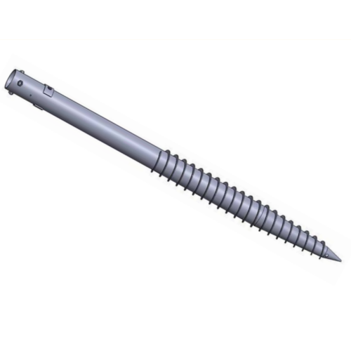
Read the Editorial PolicyGround screws for solar panels can serve a structural foundation, but that does not automatically make them an acceptable earth electrode. Use a ground screw electrically only when the adopted rules recognize the exact electrode type, the electrical design defines its function, every intended connection and current path is controlled, corrosion and lightning interfaces are resolved, and project tests verify the installed arrangement. Otherwise, treat the ground screw as a foundation, bond the required exposed conductive parts through the approved PV arrangement, and provide the grounding-electrode system specified by the electrical design. Record the decision in an Earth-Function Boundary Record before foundations or bonding hardware are released.
Separate Four Systems Before Choosing One Piece of Metal
The phrase “the pile is already in the ground” collapses several different safety and engineering functions. Separate them first. One component may contribute to more than one function, but only after each function has its own design basis and acceptance evidence.
| System or function | Primary purpose | Typical controlling information | What the ground screw does not prove by itself |
|---|---|---|---|
| Structural foundation | Transfers array actions into the ground | Geotechnical model, structural reactions, foundation design, installation and load evidence | Electrical continuity, electrode suitability or fault protection |
| Equipment bonding | Connects exposed conductive parts into the intended protective path | PV electrical design, evaluated component combinations, joint details and continuity records | Effective connection to earth or lightning-current capability |
| Grounding-electrode system | Provides the designed electrical connection to earth and coordinates the electrodes required by the installation | Adopted electrical rules, earthing design, electrode layout, conductor and connection details, tests | Structural capacity or automatic acceptance of every buried metal item |
| Lightning-protection earth termination | Forms part of an intentional lightning protection system where required | Lightning-risk decision, LPS design, separation/bonding rules, touch/step-voltage measures and inspection | That ordinary PV bonding or an unevaluated foundation can carry the assigned lightning duty |
This distinction matters because a structural joint is accepted for load transfer, while an electrical joint is assessed for a defined conductive function. A bolted sleeve, flange, shim, painted interface or adjustable head may be structurally adequate without being the approved bonding path. Conversely, a bonding device evaluated with a PV rail and module frame does not prove that the buried foundation satisfies the project’s earth-electrode requirements.
The current official scope of IEC 62548-1:2023 with Amendment 1:2025 includes PV-array wiring, protection, switching and earthing provisions and notes revised mounting-structure requirements. It places the electrical and mounting interfaces in one array-design context, but it does not turn every mounting component into an electrode. The project must apply the edition and national rules it has actually adopted.
Run the Electrode Applicability Gate
Do not begin with a resistance target or a catalogue claim. First determine whether the proposed use is recognized and whether the exact installed configuration is within the design basis.
| Gate question | Evidence to review | Proceed signal | Hold or separate-electrode signal |
|---|---|---|---|
| Does the adopted rule recognize this kind of buried metal support as an electrode? | Applicable code, national adoption, project specification and authority interpretation where required | The definition and all stated construction conditions apply | The project relies only on the words “steel” and “in soil” |
| Has the electrical designer assigned the ground screw a named function? | Single-line or earthing diagram, calculations, specifications and interface schedule | Foundation, bonding and electrode roles are explicitly distinguished | The role appears only in a supplier drawing or field assumption |
| Does the exact product and installation satisfy that role? | Geometry, material, coating, installed embedment/contact condition, joints and approved installation method | The installed configuration matches the evaluated design | A different head, extension, coating, soil zone or installation state is being substituted |
| Is the complete conductive path controlled? | Connection details, conductor route, compatible hardware, contact surfaces and continuity plan | Every interface has an owner and acceptance method | Current must cross unidentified mechanical joints or removable parts |
| Are other electrodes and lightning requirements coordinated? | Grounding-electrode layout, bonding plan, LPS decision and utility/AHJ requirements | The ground screw is integrated into one approved system | It creates an isolated, competing or undocumented earth path |
| Can the result be verified and maintained? | Inspection/test plan, access, as-built record, retest triggers and maintenance plan | Acceptance evidence will represent the installed population | The critical connection becomes buried or inaccessible without a record |
The possible outputs are not simply yes or no. The electrical authority may release the screw as a structural foundation only; accept it as a bonded structural component while retaining a separate electrode arrangement; include it as one evaluated electrode within a coordinated system; or reject the proposed electrical use. Record the chosen state by foundation type and site zone rather than assuming one answer covers the whole project.
IEC 60364-5-54:2011 with Amendment 1:2021 addresses earthing arrangements, protective conductors and protective bonding conductors. Its official description also identifies mechanical characteristics of earth electrodes and information on foundation and soil-embedded electrodes. That scope illustrates why electrode suitability is a designed installation issue. The licensed standard, local adoption and project authority—not this article—set the actual criteria.
Trace the Path, Not Just the Parts
If a ground screw has an electrical role, draw the proposed current path from each relevant exposed conductive part to the point where the project intends it to connect to earth or to the wider grounding system. Do not skip a joint because it is large, metallic or structurally tight.
Build a Conductive Path Audit Matrix:
| Path segment | Identity and configuration to freeze | Failure or change to consider | Verification owner and record |
|---|---|---|---|
| Module frame to clamp or approved bonding device | Exact module, clamp/device, rail and installation orientation | Different module frame, clamp position, surface condition or hardware | Approved product/system information and installation inspection |
| Rail or purlin across splices | Profile, splice type, bonding device and movement detail | Thermal movement, substituted splice, coating or loose/missing hardware | Electrical detail plus continuity inspection/test where required |
| Racking frame to post | Member and connection family, intentional bonding point and protected conductor route | Replaceable joint, isolator, paint, corrosion pair or field repair | Interface inspection and marked as-built detail |
| Post or adapter to ground-screw head | Head, sleeve/flange, bolts, shims and any dedicated jumper | Adjustment breaks continuity; joint changes after survey or repair | Joint-specific acceptance record |
| Ground-screw body and extensions | Product ID, material, coating, extension/coupler details and installed state | Coupler not evaluated electrically, installation damage or unrecorded replacement | Product traceability, installation log and applicable test evidence |
| Connection to the wider grounding-electrode system | Conductor, connector, accessible/test point and system node | Incompatible metals, inaccessible connection or isolated electrode | Electrical inspection, test result and as-built earthing drawing |
A low-resistance reading across one accessible joint, if the project requires it, answers only the test question and configuration represented. It does not by itself establish electrode recognition, long-term corrosion performance, adequate fault protection, lightning performance or compliance across every pile. Likewise, an earth test result is not a structural load test. Preserve the question, method, instrument, conditions, locations and acceptance authority with each result.
UL Solutions explains that UL 2703 covers PV mounting systems, mounting devices, clamps and ground lugs and includes bonding and grounding considerations. Its code-authority guidance further warns that a listing must be checked for the specific intended use and component combination. Where this route is relevant, verify the actual certification information and installation criteria; do not extend a rail-and-module bonding evaluation to a ground screw unless the documented scope explicitly supports that conclusion.
Keep Structural and Electrical Releases Synchronized
Foundation procurement often precedes final electrical detailing. That sequence can lock in an unusable assumption: the civil or structural package orders a ground-screw head and coating before the electrical package defines its connection, access and corrosion requirements.
Create one Earth-Function Boundary Record for every foundation family or zone. At minimum, include:
- foundation type, product/configuration ID and applicable site zones;
- structural role and controlling foundation documents;
- bonding role, if any, and the exact joints expected to maintain continuity;
- electrode role, if any, and the adopted-rule basis for recognizing it;
- lightning-protection status and the party responsible for that separate decision;
- conductor, connector, contact-surface and access requirements;
- material/coating/corrosion compatibility review status;
- inspection and test records required before covering or energization;
- approving authorities, release state, conditions and reopen triggers; and
- as-built and maintenance-record destination.
Use the record at three releases. Before procurement, it prevents the structural bill of materials from freezing an incompatible head or interface. Before installation, it aligns drawings, hardware, tools, inspection points and responsibilities. Before covering or energization, it checks that the installed configuration and evidence still match the approved design.
The Fixed-Tilt Solar Mounting Components guide owns the wider component and bill-of-material interface. This article adds a narrower rule: any component assigned both a mechanical and an electrical function must be released for both functions. Mechanical approval must not be presented as permission to energize.
Design for Soil, Coatings, Joints and Change
Earth-electrode behavior depends on the complete installed system and environment, not only the ground screw’s nominal steel grade. Soil conditions, moisture and chemistry can vary by zone. Coatings, cut edges, installation damage, dissimilar-metal connections and current-carrying interfaces can alter durability or contact conditions. The competent project parties must decide what investigations, material combinations, protection details, allowances, tests and maintenance are required.
Do not remove a specified protective coating or expose base metal merely to create an improvised bonding point. Use an approved connection detail that reconciles electrical contact with corrosion protection and repair requirements. If a welded tab, drilled hole, clamp, lug or conductor attachment is proposed, review its structural, fatigue, coating, galvanizing, fabrication, access and inspection consequences before release.
The Corrosion Design for Ground Screws, Solar Mounting and Structural Steel guide explains the broader exposure and durability route. For an electrically functional ground screw, add the electrode and bonding duties to that durability basis. Do not infer a universal service life from galvanizing, a soil label or a successful test on another site.
Reopen the earth-function decision when any of the following changes:
- the adopted electrical or lightning-protection basis;
- array electrical architecture or equipment-bonding route;
- ground-screw type, geometry, material, coating, head or extension;
- racking connection, adjustment, isolator, fastener or bonding device;
- site grading, soil/water condition or defined foundation zone;
- conductor material, connector, contact preparation or test point;
- installation damage, field repair, refusal response or replacement route; or
- test method, acceptance basis or responsible authority.
The change review must identify existing installed work. Updating the next purchase order does not resolve piles already buried, joints already covered or tests performed on the superseded configuration.
Coordinate Lightning Protection as Its Own Decision
Do not use “grounded” as shorthand for lightning protection. An equipment-bonding path, a grounding electrode and a lightning-protection earth-termination arrangement can interact, but they address different design questions.
The official scope of IEC 62305-3:2024 covers the design, installation, inspection and maintenance of lightning protection systems and measures addressing touch and step voltages near an LPS. IEC TR 63227:2020 specifically addresses protection of PV power-supply systems against lightning and atmospheric surge effects where such protection is required. These references do not mean every solar farm requires the same LPS, nor do they authorize an ordinary ground screw as an LPS electrode.
Record whether a lightning-risk assessment or project rule requires an LPS, who owns its design, how any foundation metal is included or separated, how equipotential bonding and surge-protection interfaces are coordinated, and what inspection/test evidence is needed. If that decision is pending, mark it as a hold on the affected electrical interface rather than allowing the structural installation to imply closure.
Verify the Installed Arrangement and Preserve the Evidence
Verification should follow the claimed function. A structural foundation needs its structural and geotechnical evidence. An intentional bonding path needs the inspections and electrical tests defined for that path. An earth electrode needs the project’s electrode acceptance evidence. An LPS interface needs the records required by its design and applicable rules. One result cannot be silently reused for all four.
Use a verification and handover schedule:
| Stage | Evidence to capture | Decision enabled | Reopen trigger |
|---|---|---|---|
| Design release | Function boundary, adopted basis, exact configuration, drawings and responsible approvals | Procure or hold the dual-function interface | Design, product, zone or authority changes |
| Incoming and pre-installation | Product identity, material/coating record, connector/bonding hardware and approved method | Release identified materials to the workfront | Substitution, damage or missing traceability |
| Installation before concealment | Location, installed configuration, joint/contact condition, conductor connection, repair and inspection results | Cover, connect or hold the location | Adjustment, repair, replacement or inaccessible evidence gap |
| Electrical verification | Test plan, instruments, conditions, test points, results, interpretation and acceptance | Accept the claimed electrical function for a defined scope | Failed/unstable result, changed conditions or unrepresented zones |
| Handover and operation | As-built earthing drawing, foundation/electrode register, exceptions, maintenance access and retest triggers | Transfer a maintainable system record | Alteration, corrosion finding, damage or changed electrical/LPS arrangement |
The test plan should state what each test demonstrates and what it does not. Soil and environmental conditions at the time of testing may matter to interpretation, so preserve them where the appointed authority requires. Define how results represent multiple piles or zones; do not let one convenient test point stand for an uncontrolled population.
The Ground Screw Pile Installation guide owns structural installation hold points and production records. Add the electrical witness, connection and test requirements to the work package before the relevant interfaces become inaccessible. The final as-built record should let an operator locate every intentional electrode and test point without reverse-engineering the racking.
Ground screws for solar panels may be part of an earth arrangement, but only by design—not by vocabulary, appearance or convenience. Define the four functions, run the applicability gate, audit every conductive interface and verify the installed configuration under the project’s electrical and safety authorities. If that evidence chain is incomplete, preserve the ground screw’s structural role and use the separately approved grounding arrangement.
Related Resources
- Ground Screw Piles for Solar Farms owns the commercial application and enquiry route for solar-foundation products.
- Fixed-Tilt Solar Mounting Foundation: Prove Each Zone controls the structural and geotechnical foundation-route decision.
- Fixed-Tilt Solar Mounting Components: Control Every Interface controls the complete mounting assembly and bonding-accessory bill of materials.
- Ground Screw Pile Installation: Control Every Hold Point defines structural installation releases and traceable field records.
- Corrosion Design for Ground Screws, Solar Mounting and Structural Steel develops the wider durability basis for buried and exposed steel.
References
- IEC 62548-1:2023 with Amendment 1:2025 — Photovoltaic arrays, design requirements
- IEC 60364-5-54:2011 with Amendment 1:2021 — Earthing arrangements and protective conductors
- UL Solutions — PV Mounting Systems Certification and UL 2703 scope
- IEC 62305-3:2024 — Protection against lightning, physical damage and life hazard
- IEC TR 63227:2020 — Lightning and surge-voltage protection for PV power-supply systems
Next Step: Issue the Earth-Function Boundary Record
Before ordering ground screws or releasing bonding details, identify the project country and adopted electrical rules, array/racking arrangement, ground-screw type and zones, structural connection, proposed bonding and electrode functions, lightning-protection status, materials/coatings, electrical connection details, inspection/test plan and responsible approvers. Mark every unresolved function as a hold or a separately provided system.
Send that controlled input set to info@baolaipipes.com through the Ground Screw Piles for Solar Farms route for a supplier-side product and interface review. East Baoyu can clarify available ground-screw configurations and supplier records within an agreed enquiry. Electrical design, code interpretation, grounding-electrode acceptance, lightning protection, structural/geotechnical design, installation safety, testing, energization and final approval remain with the project’s appointed qualified parties and authorities.
References, disclosure and change record
References and further verification
- https://webstore.iec.ch/en/publication/64171
- https://webstore.iec.ch/en/publication/1882
- https://www.ul.com/services/pv-mounting-systems-certification
- https://eastbaoyu.com/fixed-tilt-solar-mounting-components/
- https://eastbaoyu.com/corrosion-design-ground-screws-solar-steel/
- https://webstore.iec.ch/en/publication/33680
- https://webstore.iec.ch/en/publication/64039
- https://eastbaoyu.com/ground-screw-pile-installation/
- https://eastbaoyu.com/screw-piles/solar-farms/
- https://eastbaoyu.com/fixed-tilt-solar-mounting-foundation/
Disclosure: East Baoyu manufactures and supplies products discussed on this website. Structured drafting tools may assist research and editing, but technical claims, project inputs and release decisions require qualified review under the applicable project responsibilities.
Version 1.0: Scheduled as EB50-029 on 2026-09-05.
View the public Content Change Log · Corrections: info@baolaipipes.com