

Authorship, review and evidence boundary
- Technical review
- East Baoyu Engineering Editorial Team
- Reviewed
- 2026-08-24
- Scope
- General engineering and procurement guidance. This article is not a project-specific design, capacity statement, certificate, warranty, code interpretation or contract requirement.
Evidence basis: Official and public references identified in the article. Project values and release decisions require qualified review under the applicable project responsibilities.
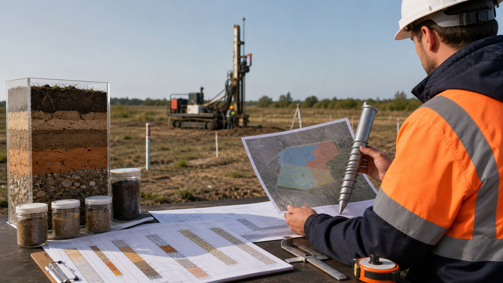
Read the Editorial PolicyCan screw piles be installed in rocky ground? Sometimes—but only after “rocky” is replaced by a location-based ground description and the project defines what happens when penetration changes. Weathered or fractured rock, an isolated boulder, coarse fill and shallow competent rock create different installation and load-transfer questions. A borehole label, a sudden torque increase or early refusal does not answer those questions by itself. Before production, map the condition by zone, check the proposed pile and equipment limits, run controlled trials under approved stop criteria, and choose one route: direct installation, a reviewed method change, engineered relocation or another foundation concept.
Treat rocky ground as several different conditions
“Rock” is not one material, and “rocky” is not an engineering classification. A useful log separates the intact material from rock-mass features such as bedding, joints, faults, fractures and other discontinuities. The British Geological Survey Rock Classification Scheme provides controlled terms for geological materials and rock discontinuities. Those descriptions matter because the installation response can depend on whether the pile meets a progressive weathering transition, fractured rock, an abrupt competent surface or separate particles within soil.
The description still does not predict screw-pile suitability. It must be connected to the pile geometry, installation method, required founding condition, structural actions and allowable movement. A rock core at one borehole is evidence at that coordinate; it is not proof of the condition at every foundation point.
| Reported or observed condition | What it may mean for installation | What remains unproven | First decision question |
|---|---|---|---|
| Weathered or fractured rock transition | Progressive penetration and seating may be possible for a suitable system | Continuity, strength, penetration response and final load transfer | Is a controlled direct-installation trial justified in this zone? |
| Abrupt shallow hard-rock surface | The helix may not penetrate or seat as assumed | Rockhead shape, interface condition and acceptable founding mechanism | Does the design allow a reviewed method change, or is another foundation needed? |
| Cobbles, boulders or very coarse gravel | Local deflection, interruption or loss of positional control may occur | Particle distribution, bypass space and pile-head tolerance | Is the issue isolated enough for an engineered relocation rule? |
| Made ground or buried debris | A hard response may come from an obstruction rather than geological rock | Object type, extent, contamination, services and surrounding support | Must the area be investigated or cleared before any trial? |
| Variable rockhead across a large layout | Different pile points may reach different transitions or refusal elevations | Zone boundaries and representativeness of investigation points | How many trial and alternate-foundation zones are needed? |
Engineering New Zealand Practice Note 28 identifies hard rock, hard layers and obstructions as conditions that can prevent embedment or accurate placement. It also notes that a gradual weathering profile may be more compatible with full helix seating than an abrupt hard-rock interface. This is useful screening guidance, not a promise that any pile will penetrate or be accepted.
Map the condition against the actual foundation layout
A rocky-ground decision begins with a ground model, not a generic soil note. The European Commission JRC guideline on assembling the ground model treats it as a site-specific interpretation assembled from investigation and other available data, including rockhead and structural geology. It also recognizes that the model is progressively updated as knowledge increases.
For a screw-pile package, plot factual evidence against the same coordinates and datum as the foundation layout. Useful records can include boreholes, rock cores, test pits, probing, exposures, geophysics, previous excavation records and trial installations. Preserve the distinction between:
- Observed: the material or response recorded at a known location and elevation.
- Interpreted: the probable rockhead, transition or obstruction zone between observations.
- Unproven: the condition outside reliable coverage or below the explored depth.
Then overlay the structural information. A small permitted shift may bypass an isolated obstruction for one support, while the same shift may be unacceptable where it creates connection eccentricity, clashes with a rail or changes the supported frame's load path. Rock evidence therefore has to be read with pile coordinates, top elevations, reactions, connection geometry and construction tolerances.
Do not collapse the model into an average rock depth. Show the range, abrupt changes and confidence by zone. If the lowest confidence occurs where the loads or movement sensitivity are highest, assign additional investigation or a more conservative trial gate there. The objective is not to eliminate geological uncertainty; it is to make the remaining uncertainty visible before it reaches the crew.
Select one of four routes before mobilisation
The team should agree the available routes before equipment arrives. This prevents a commercial commitment to one installation method from becoming the field decision rule.
| Controlled route | When it may be considered | Evidence required before release | What it does not prove |
|---|---|---|---|
| A. Direct-installation trial | Evidence suggests a penetrable transition or fractured profile, and the candidate pile/equipment remain within known limits | Defined trial locations, pile revision, tooling, equipment, measurement method, stop criteria and verification plan | Production suitability or capacity outside the approved trial scope |
| B. Reviewed method or configuration change | A hard layer or recurring obstruction is anticipated and an engineered alternative—such as different approved tooling, lead geometry or pilot operation—is being assessed | Revised method, pile/component checks, ground-disturbance assessment, acceptance basis and accountable approval | That a field modification preserves the original capacity or durability assumptions |
| C. Engineered relocation | Evidence indicates isolated obstructions and the supported structure permits a controlled offset | Permitted plan/elevation tolerance, revised connection/load-path check, survey control and as-built rule | That repeated relocations are harmless or that the whole zone is suitable |
| D. Alternate foundation concept | Required penetration or seating cannot be achieved within approved limits, variability is too high, or the consequence of uncertainty is unacceptable | New geotechnical/structural concept, interface design, construction method, verification and commercial boundary | That one alternative is universally preferable in rock |
These routes are not a ranking. Route A can be inappropriate where the evidence is weak; Route D can be the most controlled choice when competent rock or widespread boulders make the intended screw mechanism unreliable. Likewise, predrilling or special tooling is not automatically a compromise between the two. It can change disturbance, seating, installation records and the evidence needed for acceptance, so it belongs under an approved revised basis.
The selected route should name its owner and fallback. For example: “Trial Route A at locations T-01 to T-04; if the approved loss-of-advance or component-limit trigger occurs, stop and return to engineering review. Do not move to Route B or C without a recorded disposition.” That statement is far more useful than “install to refusal.”
Design a trial that can answer “no”
A trial is valuable only if the project can accept an unfavourable result without improvising. Its purpose is to test a defined hypothesis: whether a named pile, tooling and equipment configuration can be installed in a named ground zone while preserving geometry and staying within approved limits. Capacity verification is a separate objective unless the test plan explicitly combines them.
Before the trial, release a controlled card containing:
- trial location, coordinates, ground level and assigned ground zone;
- nearby investigation references and the expected rock/obstruction elevation range;
- pile, coupling, head, lead and tooling revisions;
- installation machine and measurement-system identification;
- planned orientation, target geometry and permitted positional/alignment tolerances;
- measurements to record against depth or elevation, including advance, rotations and torque where applicable;
- approved component, tooling and equipment limits;
- stop triggers for loss of advance, excessive response, deviation, damage or unreliable measurement;
- inspection, extraction, replacement and verification actions after an interruption; and
- the person authorized to classify and dispose of each outcome.
The Engineering New Zealand screw-pile practice note links installation equipment selection to torque requirements, pile torsional capacity, access, ground conditions and positional tolerance. It also calls for site-specific investigation and construction records. The adopted project method, local safety rules and manufacturer information still control the actual trial. Underground-service clearance, exclusion zones, equipment stability and operator competence must be closed in that method rather than inferred from this article.
Record the response continuously enough to distinguish a gradual change from a short local interruption. A final number without the depth/elevation history can hide where the event occurred. Photograph or inspect an extracted trial pile when the approved plan calls for it, and retain damage observations with the trial record. An apparently successful penetration is incomplete evidence if the helix, shaft, connection or coating condition is unknown.
Turn refusal into a hold point, not a field verdict
For this workflow, “refusal” should mean a project-defined observation: the required advance cannot be achieved under the approved method without reaching a stop trigger or limit. It should not be a universal torque number, rotation count or operator impression. The event starts a review; it does not finish one.
First verify the evidence chain. Was the location correct? Was the reference level current? Did the pile and tooling match the released revision? Was the measurement system within its calibration status? Did the machine reach an equipment limit, or did the pile show distress first? Did the response occur at an elevation consistent with the interpreted rockhead, or only at one point with no matching nearby evidence?
Possible causes stay provisional until reviewed. An early hard response may indicate a boulder, buried concrete, dense fill, a rock ledge, an equipment constraint or a damaged component. Rotation with little advance can also affect the material around the helix. None of those observations alone proves competent bearing, acceptable seating or service capacity.
The installer should have authority to stop under the approved method. The appointed engineering authority should own the disposition: continue under the same released rule, perform additional investigation, revise and retrial the method, relocate within an approved tolerance, replace the affected pile, or change the foundation concept. Record the decision before work resumes.
Keep installability separate from capacity and interface fit
Rocky-ground reviews often fail because a high installation response is allowed to answer several different questions. Keep at least five checks separate:
- Installability: can the pile reach the required geometry without unacceptable damage or loss of control?
- Component resistance: can the shaft, helix, couplings, welds, head and tooling withstand the approved installation and service actions?
- Ground resistance and movement: does the installed foundation satisfy the required compression, uplift, lateral, moment and serviceability criteria under the adopted design basis?
- Interface fit: do the final location, inclination, elevation and head detail preserve the supported structure's load path and tolerances?
- Applicability: do the calculation, trial, test and installation records apply to this pile revision and ground zone?
The current ICC-ES AC358 provides one US evaluation context for helical pile systems and devices. It separates component/system considerations from soil capacity and requires defined testing to establish torque correlations within its scope. That illustrates the evidence boundary; it does not create an East Baoyu evaluation report or a rocky-ground acceptance rule for an arbitrary project.
Use the same discipline for project evidence. A direct-installation trial can show that one configuration reached a recorded elevation without a declared stop event. A load test can show the measured response of the tested element under its method and conditions. A structural calculation can check named components and actions. The approved capacity basis must connect these records; no single observation should silently replace the rest.
If the helix bears partly on an irregular surface, if a pilot operation changes the surrounding material, or if relocation changes the connection eccentricity, return to the responsible designers. Those are changes to the assumed system, not minor production notes.
Release production by zone, with an exception route
After investigation and trials, turn the learning into a controlled release register. Do not simply attach trial logs to an email and tell the crew to “follow the successful one.”
| Release field | What to record | Why it controls the decision |
|---|---|---|
| Zone ID and boundary | Drawing revision, coordinates/elevations and confidence limits | Prevents a local result from being applied outside its evidence area |
| Ground basis | Factual records, interpreted condition and unresolved variability | Shows what the approved method assumes |
| Pile/method configuration | Pile, lead, coupling, tool, equipment and method revisions | Keeps field work aligned with the reviewed system |
| Installation acceptance basis | Project-defined depth/elevation, advance/response, alignment, damage and record requirements | Makes acceptance measurable without inventing universal thresholds |
| Verification scope | Trial or production tests, inspections, frequencies and applicability | Connects observations to the required performance decision |
| Exception triggers | Loss of advance, abnormal response, deviation, damage, missing data or out-of-zone condition | Starts the hold point before assumptions are exceeded |
| Disposition authority | Named role, record form and permitted outcomes | Prevents unapproved field changes |
| Release status | Approved for defined production, restricted trial only, further investigation, alternate foundation or hold | Gives procurement and construction one current decision |
Each installed foundation should retain a location ID linked to the pile revision, ground zone, equipment or rig, installation record, exception status, test status and as-built survey. When several trials show a consistent response, the geotechnical reviewer may revise the zone interpretation and release basis. When the response changes, narrow the zone or reopen it. The JRC ground-model guidance supports this progressive-update logic: new field evidence should improve the model, not disappear into an isolated installation log.
Decision boundary: screw piles in rocky ground are neither automatically suitable nor automatically excluded. A responsible release states the defined condition, the selected pile and method, the limits, the evidence, the zone and the exception route. If the pile cannot reach or preserve the assumed geometry within approved component and equipment limits, stop treating installation as a production problem. Return the observation to the ground model and choose a reviewed method, engineered relocation or alternate foundation. The next useful deliverable is a zone-based trial and disposition register—not a universal rock claim.
Related Resources
- Ground Screw Selection from Site Investigation — the full route from ground model and loads to a preliminary pile concept.
- Geotechnical Data Needed Before Specifying Ground Screws — how to judge whether the available investigation can support the next decision gate.
- Ground Screw Design Input Checklist — the loads, interfaces, durability, installation and verification inputs needed before a pile schedule is released.
- Installation Torque and Ground Screw Capacity — the limits of torque correlation and production control.
References
- British Geological Survey — Rock Classification Scheme. Used for controlled geological-material and discontinuity terminology, not pile suitability.
- European Commission JRC — Assembling the ground model and the derived values. JRC140556, 2024. European application guidance; the project's adopted rules control.
- Engineering New Zealand — Practice Note 28: Screw Piles. Version 1, October 2015, currently listed by Engineering NZ. New Zealand practice guidance, not a universal project specification.
- ICC-ES AC358 — Helical Pile Systems and Devices. AC358 (24), used only to illustrate bounded system and test evidence in its US evaluation context.
- East Baoyu Screw Piles. Current product-data and responsibility boundary; catalogue examples are not a project pile schedule.
Next Step: Submit the Rocky-Ground Trial Inputs
Send the foundation layout and levels, ground model and factual logs, rock or obstruction evidence, project reactions and tolerances, proposed pile/tool/equipment information, and the intended trial and exception basis. East Baoyu can identify missing supplier inputs and provide available product, material and interface information within the agreed supply scope.
The project's appointed geotechnical, structural and installation professionals remain responsible for the ground interpretation, foundation design, method, safety controls, trials, testing, acceptance and final release. Contact East Baoyu or email info@baolaipipes.com.
References, disclosure and change record
References and further verification
- https://www.bgs.ac.uk/technologies/bgs-rock-classification-scheme/
- https://www.engineeringnz.org/documents/92/Practice_Note_28_Screw_Piles_Guidelines_for_Design_Construction_and_Installation.pdf
- https://eurocodes.jrc.ec.europa.eu/publications/assembling-ground-model-and-derived-values
- https://www.engineeringnz.org/engineer-tools/engineering-documents/practice-notes-and-guidelines/
- https://icc-es.org/evaluation-report-listing/ac358/
- https://eastbaoyu.com/ground-screw-selection-from-site-investigation/
- https://eastbaoyu.com/geotechnical-data-needed-before-specifying-ground-screws/
- https://eastbaoyu.com/ground-screw-design-input-checklist-epc-procurement-teams/
- https://eastbaoyu.com/installation-torque-and-ground-screw-capacity/
- https://eastbaoyu.com/screw-piles/
- https://eastbaoyu.com/contact/
Disclosure: East Baoyu manufactures and supplies products discussed on this website. Structured drafting tools may assist research and editing, but technical claims, project inputs and release decisions require qualified review under the applicable project responsibilities.
Version 1.0: Scheduled in the East Baoyu 30-article engineering knowledge-base batch on 2026-08-25.
View the public Content Change Log · Corrections: info@baolaipipes.com