

Authorship, review and evidence boundary
- Technical review
- East Baoyu Engineering Editorial Team
- Reviewed
- 2026-09-05
- Scope
- General engineering and procurement guidance. This article is not a project-specific design, capacity statement, certificate, warranty, code interpretation or contract requirement.
Evidence basis: Official and public references identified in the article. Project values and release decisions require qualified review under the applicable project responsibilities.
Read the Editorial PolicyA helical foundation is not complete when the pile shaft reaches the required depth. The project still needs a defined route from the supported structure, through a bracket, cap, footing or grade beam, into the pile and then the ground. That upper interface changes with the job. New construction can coordinate concrete and embedded details before casting. Work on an existing foundation must first expose, assess and protect a structure that is already carrying load. Treating both as the same connection detail can leave load direction, geometry, temporary support and acceptance responsibility unresolved. Choose the interface scenario first, then release the foundation as a complete load path.
Separate New Construction from Existing-Foundation Work
Classify the work before choosing a bracket or issuing a pile schedule. “Helical foundations” can mean new deep foundations, support beside an existing footing, underpinning to arrest movement, or a controlled lifting operation. Those situations do not share one default interface or sequence.
Current ICC-ES reports show why the distinction matters. ESR-3032 describes repair brackets for gravity-load support from existing concrete foundations and new-construction brackets cast into new concrete. ESR-3982 describes compression-only repair brackets for its underpinning use and new-construction brackets for the load directions defined in that report. These are product-specific examples, not universal rules or East Baoyu certifications (ICC-ES ESR-3032; ICC-ES ESR-3982).
Use this first decision matrix to define the project route.
| Interface scenario | Existing condition | First engineering question | Evidence needed before detail release | Early stop condition |
|---|---|---|---|---|
| New concrete cap, footing or grade beam | Concrete and reinforcement can still be coordinated | Which compression, tension, lateral and moment actions must cross the interface? | Project reactions, interface model, concrete geometry, reinforcement concept, pile position and connection detail | Load directions or concrete responsibility are not assigned |
| New steel or modular support | The supported steel interface can be designed with the foundation | How are bearing, uplift, shear, moment and tolerances transferred without unintended prying or eccentricity? | Base/interface drawing, load combinations, fastener or weld basis, adjustment strategy and erection tolerances | The termination is selected before the structural load path is defined |
| Existing footing support or underpinning | The structure is already loaded and its condition may be uncertain | Where can load be collected without damaging weak or deteriorated material? | Condition survey, footing geometry, reinforcement information, load-transfer sequence and monitoring criteria | The bearing zone, foundation condition or temporary-support route is unknown |
| Existing-foundation lifting or level recovery | Controlled movement is proposed after support is installed | What movement is permitted, and who controls the lift? | Structural assessment, lift points, synchronized procedure, limits, instrumentation and signed release authority | A target elevation is stated without movement limits or an engineered procedure |
If a project contains several scenarios, divide it into zones. A new extension beside an existing building may need both a new-construction and an underpinning detail.
Draw the Complete Load Path Before Selecting the Head
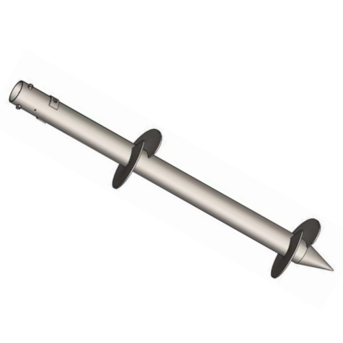
The head connection cannot be checked from a catalog image. Draw each link from the supported element to the ground and put the design action at every transfer. UFGS 31 63 26.60 defines a helical pile as a shaft with one or more helix plates plus a load-transfer device for attachment to the structure. It also calls for drawings to identify locations, loads, pile types, geometry and soil information. The guide is an editable project specification, not a ready-made design (WBDG, UFGS 31 63 26.60).
Create one load-path row for every materially different support condition.
| Load-path link | Input to define | Check to complete | Evidence at release |
|---|---|---|---|
| Supported structure | Reactions, combinations, movement limits and construction state | Confirm whether compression, uplift, shear, moment, eccentricity or cyclic effects apply | Controlled reaction schedule and model reference |
| Bracket, cap or termination | Product/configuration identity and contact geometry | Check bearing, fasteners, welds, local plate behavior, fit and permitted load directions | Approved interface drawing and calculation reference |
| Concrete or steel receiving element | Dimensions, material, reinforcement or member details | Check local load introduction, edge distance, breakout/splitting, yielding, distortion and constructability as applicable | Structural detail coordinated with the interface |
| Pile shaft and couplings | Exact sections, connection sequence, unbraced length and cut-off | Check axial, bending, shear, torsion and interaction under the adopted model | Pile schedule and component traceability |
| Helices and surrounding ground | Ground profile, water conditions, helix geometry, installation response and test basis | Establish site-specific resistance and movement under the required actions | Geotechnical basis, calculation and verification route |
Do not let one capacity number close the whole row. Soil resistance does not verify a bracket, and a bracket table does not verify the existing footing. An installation-torque record does not establish every structural and serviceability limit. The Ground Screw Load Capacity guide checks which link governs the installed system.
The load path must also show restraint assumptions. If lateral load or moment is resisted partly by a grade beam, slab, pile group or supported frame, name that element and the construction stage at which it becomes effective. Otherwise, two designers may each assume the other system provides restraint.
Freeze New-Construction Geometry Before Concrete Release
New construction offers coordination time, but only if the interface is released before the concrete or steel receiving element becomes irreversible. Define the pile coordinates, inclination, top elevation, cut-off rule, head orientation, embedment or bearing arrangement, adjustment allowance and required clearances. Coordinate those values with reinforcement, anchor assemblies, sleeves, formwork and erection access.
The selected head must match the actions and the adopted product evidence. ESR-3032, for example, describes its named new-construction bracket as a plate cast into a concrete grade beam, footing or pile cap, with project-specific embedment and edge distance shown in approved plans. It also requires the foundation concrete to be cast around the bracket. That detail illustrates a coordination dependency: after the concrete is placed, a pile-position or bracket-geometry conflict is no longer a simple drawing correction (ICC-ES ESR-3032).
Set a pre-concrete hold point with four checks:
- Survey: confirm actual pile position, inclination and top elevation against the tolerance basis.
- Disposition: close every out-of-position, damaged or short/long pile through the responsible engineer.
- Interface fit: verify the exact termination, contact surface, fasteners or weld preparation and corrosion-treatment restoration.
- Receiving element: confirm concrete geometry, reinforcement, edge distances, openings and pour sequence against the approved interface detail.
The UFGS example requires an as-installed survey after each pile group and before concrete placement, with actual location and top elevation shown for review. It separately lists pile connections, splices, placement and the as-installed survey as submittal items. Project teams must replace its bracketed choices and acceptance values with their own requirements, but the release sequence is clear: survey and disposition precede concealment (WBDG, UFGS 31 63 26.60).
Treat Underpinning as a Controlled Transfer of Existing Load
Existing-foundation work begins with added uncertainty. Drawings may be incomplete, and concrete, reinforcement, cracks, repairs or actual bearing level may differ from records. Utilities and finishes can restrict access. The structure may already be moving. Start with a condition and geometry investigation, not a bracket selection.
Document at least:
- the supported wall, column, footing, grade beam or slab geometry;
- material condition, visible distress and previous repairs;
- reinforcement or embedded items where known and how they were located;
- actual load collection point and any eccentricity between the structure and pile axis;
- excavation limits, groundwater, buried services and access for installation tooling;
- the temporary condition while soil is removed and the bracket is fitted;
- whether the objective is support, stabilization, load sharing, lifting or another defined outcome; and
- the movement quantities to monitor before, during and after transfer.
Product-specific instructions can require exposed foundation surfaces to be prepared for full contact and the attachment to be designed through approved plans. ESR-3032 also states that any lift using its repair bracket must be verified by the registered design professional so that the foundation or superstructure is not overstressed. This does not establish a universal repair procedure. It shows that contact preparation, attachment and lift control are part of the engineered interface, rather than installer improvisations (ICC-ES ESR-3032).
Use a stage gate for each underpinning location or defined group.
| Gate | Required evidence | Release authority | If the gate fails |
|---|---|---|---|
| Existing condition accepted | Survey, distress map, verified geometry, load-transfer objective and utility/access check | Structural/geotechnical leads as assigned | Hold excavation or redesign the investigation |
| Temporary condition accepted | Excavation sequence, temporary support, stability check, monitoring points and action limits | Engineer responsible for temporary and permanent works | Revise sequence or add support/monitoring |
| Pile ready for connection | Installation record, position/elevation, configuration identity, field deviations and required verification results | Foundation designer/inspector under the project plan | Quarantine the location and issue a disposition |
| Contact and attachment accepted | Prepared bearing surfaces, bracket orientation, fasteners/welds, fit and protection restoration | Structural designer and inspection authority | Correct the interface before load transfer |
| Transfer accepted | Load or movement increments, readings, observations and signed stop/continue decisions | Named lift/load-transfer controller | Stop, stabilize and follow the contingency plan |
| Permanent condition released | Final setting, locks/shims/grout as designed, as-built record and monitoring closeout | Engineer of record or contract-defined approver | Keep temporary controls and close the outstanding item |
Do not use “support installed” as the acceptance statement. Record what load-transfer objective was achieved and which residual movements, repairs or monitoring obligations remain.
Close Access, Sequencing and Existing-Structure Protection
Interface design and construction planning must meet before mobilization. Confirm that the installation unit, drive head, reaction control, extension lengths, lifting equipment and measurement devices can reach each location without removing an unapproved part of the structure. Check overhead and lateral clearance, working-platform capacity, spoil or groundwater control, component handling and safe access to the final connection.
Define the sequence by structural effect, not only by pile number. The work plan should state how many locations may be open at once, which elements must remain supported, when the pile may be cut, when the bracket may be engaged, whether preload or lift is permitted, and what happens after an unexpected movement or loss of contact. Project safety and temporary-works procedures govern execution; an article cannot replace them.
Where existing or adjacent assets may be affected, define a baseline and an action plan. UFGS 31 63 26.60 includes optional project provisions for preconstruction condition surveys, protection of existing structures and instrumentation where vibration, settlement or lateral movement is a concern. It directs the project specification to identify the facilities requiring protection and to set project-specific survey and monitoring requirements. Those clauses are not universal distances or thresholds. They demonstrate that protection limits, instrumentation, reporting and stop-work actions must be selected for the actual site (WBDG, UFGS 31 63 26.60).
Record monitoring as a decision tool. Each reading needs a location, baseline, frequency, trigger level, responsible observer and required response. Data without a pre-agreed action cannot control the transfer.
Assign Every Interface Decision to an Accountable Party
The upper connection sits between disciplines, contracts and work packages. A responsibility gap can survive even when each party has completed its own calculation. Assign one accountable output for each decision before design release:
- the structural engineer, owner and specialty foundation designer contribute to an approved reaction and serviceability schedule;
- the geotechnical engineer and foundation designer close a zone-based ground-resistance and verification basis;
- the structural engineer, specialty designer and product supplier coordinate the bracket or cap calculation with the receiving-structure drawing;
- the temporary-works designer, structural engineer and contractor release a construction method with limits and contingency actions;
- the supplier, procurement team and document controller tie the purchase description to approved models and drawings;
- the installer, inspector and foundation designer agree the method, hold points, records and deviation route; and
- the engineer of record or contract-named authority signs the as-built interface release.
Replace “by others” with a named deliverable and approver. If a specialty designer supplies only the pile and termination calculation, state who checks the existing concrete, reinforcement, steel framing, temporary works and global structural effects. If a contractor proposes a field adjustment, state whether it changes the design model and who can approve it before work continues.
Verify the Installed Interface Before It Is Hidden or Loaded
Inspection should follow the failure path. Verify identity first: shaft, extensions, couplings, termination, bracket, fasteners, coatings and drawing revision. Then verify geometry: position, inclination, cut-off, orientation, contact, edge distances and fit. Review installation and verification evidence for the exact pile. Finally, confirm the completed connection and receiving element before concealment or permanent load transfer.
Separate observations from acceptance. A photograph can show orientation, but not necessarily contact pressure or hidden reinforcement. A torque log records installation response under its defined measurement system, but does not alone verify the concrete connection. A survey records position and elevation, but does not approve a deviation. Tie each record to the requirement and approving party.
Open an interface deviation when any of these change:
- pile position, inclination or elevation exceeds the approved basis;
- the shaft is cut, drilled, welded or repaired outside the released detail;
- the proposed bracket, cap, fastener or weld differs from the approved configuration;
- existing concrete, reinforcement, geometry or distress differs from the investigation;
- full bearing/contact cannot be achieved as detailed;
- an obstruction forces a new pile location or load eccentricity;
- monitoring reaches an action level; or
- the load-transfer or concrete sequence changes.
The disposition should identify affected calculations, drawings, installation records and inspections. A field sketch without design review is not a closed interface change.
Issue a Helical Foundation Interface Record
The final deliverable should connect design intent to installed evidence in one controlled record. Use one row for each pile group or distinct interface type, and separate locations when condition or disposition differs.
| Record field | Minimum entry |
|---|---|
| Scenario and objective | New construction, support, stabilization, underpinning or controlled lifting, with the required outcome |
| Supported element | Structure/footing/member ID, condition reference and load collection point |
| Design basis | Reactions, combinations, movement limits, ground zone and governing calculation references |
| Interface configuration | Pile, shaft, coupling, head/bracket/cap, connection and receiving-element drawing revisions |
| Construction controls | Access, temporary condition, sequence, hold points, monitoring and contingency route |
| Installed evidence | Component identity, installation log, test/verification result, survey, connection inspection and protection restoration |
| Deviations | Actual condition, technical disposition, approver and affected records |
| Release boundary | Permitted use/load-transfer stage, open obligations, approving party and date |
| Change triggers | Load, geometry, product, ground, sequence, monitoring or approval changes that require recheck |
Link the accepted record to the calculation, approved drawing, purchase description, installation method and as-built package. The purpose is not to create another document for its own sake. It is to prevent the structure, connection, pile and ground from being approved in separate files without evidence that the full path closes.
Related Resources
- Screw Piles — review East Baoyu’s current product-family information and inquiry route.
- Helical Piles: Test Evaluation Evidence Against the Project — check whether a named evaluation report supports the offered configuration and project claim.
- Ground Screw Load Capacity — trace every governing structural, connection and ground-resistance limit.
- Ground Screw Pile Installation — define equipment, hold points, records and field-deviation control.
- Ground Screw Design Input Checklist — assemble load, geotechnical, interface and project information before review.
References
- ICC Evaluation Service — ESR-3032, MacLean-Dixie Helical Foundation Systems
- ICC Evaluation Service — ESR-3982, Helical Anchors Helical Foundation Systems
- Whole Building Design Guide — UFGS 31 63 26.60, Grouted Helical Piles
Next Step: Release One Complete Interface
Select one representative interface type and collect the supported-structure reactions, movement limits, ground basis, pile configuration, bracket or cap details, receiving-element geometry, installation access, sequence, monitoring needs and approval responsibilities. For existing foundations, add the condition survey and the intended support or movement outcome. Complete the Helical Foundation Interface Record and close every design or field deviation before concrete placement, concealment or load transfer.
Submit that bounded input package through Screw Piles when you need East Baoyu to identify a suitable product configuration, component-document scope and quotation inputs. The project’s appointed structural, geotechnical, temporary-works, installation, inspection and approval parties retain responsibility for design, capacity, code acceptance, construction safety and final release.
References, disclosure and change record
References and further verification
- https://icc-es.org/reports/pdf_files/ESR-3032.pdf
- https://icc-es.org/Reports/pdf_files/ESR-3982.pdf
- https://www.wbdg.org/FFC/DOD/UFGS/UFGS%2031%2063%2026.60.pdf
- https://eastbaoyu.com/ground-screw-load-capacity/
- https://eastbaoyu.com/screw-piles/
- https://eastbaoyu.com/helical-piles-evaluation-report-applicability/
- https://eastbaoyu.com/ground-screw-pile-installation/
- https://eastbaoyu.com/ground-screw-design-input-checklist-epc-procurement-teams/
Disclosure: East Baoyu manufactures and supplies products discussed on this website. Structured drafting tools may assist research and editing, but technical claims, project inputs and release decisions require qualified review under the applicable project responsibilities.
Version 1.0: Scheduled as EB50-018 on 2026-09-05.
View the public Content Change Log · Corrections: info@baolaipipes.com