

Authorship, review and evidence boundary
- Technical review
- East Baoyu Engineering Editorial Team
- Reviewed
- 2026-08-24
- Scope
- General engineering and procurement guidance. This article is not a project-specific design, capacity statement, certificate, warranty, code interpretation or contract requirement.
Evidence basis: Official and public references identified in the article. Project values and release decisions require qualified review under the applicable project responsibilities.
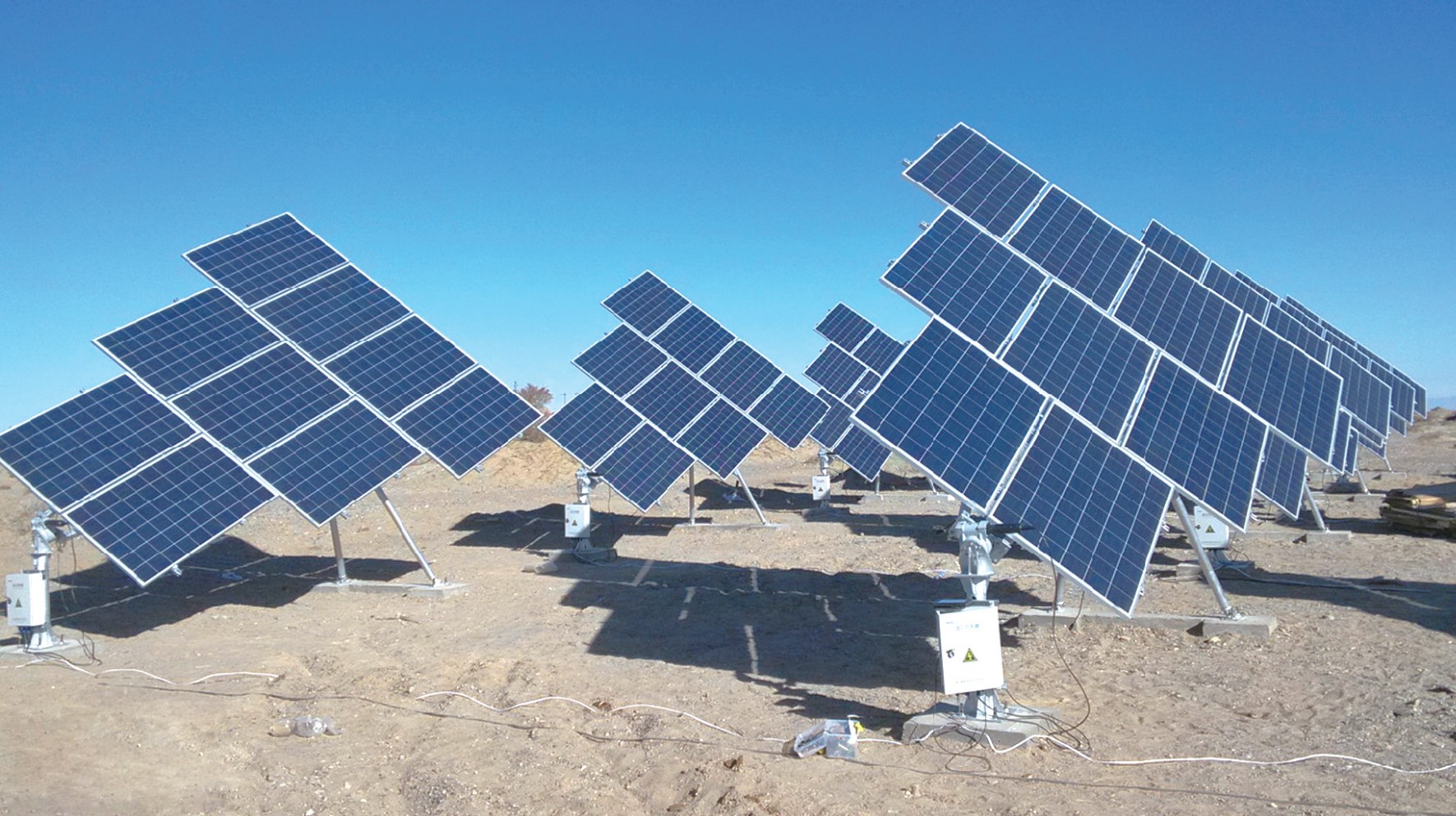
Read the Editorial PolicyA single axis solar tracker is not completely defined by saying that a row rotates about one axis. The project still has to identify that axis, divide the plant into repeatable row units, connect terrain to the energy model, map control states to physical positions, and allocate drives, sensors, power, cables, structures and foundations. If those decisions remain implicit, different teams can model or procure different systems under the same name. Freeze one revision-controlled Single-Axis Architecture Definition before releasing components or project interfaces. This guide explains what that definition should contain and how to decide whether it is ready, conditional or still on hold.
Define the Architecture Before Naming Components
Begin with the row as a system, not with a drive catalogue. The controlled object is one identifiable physical and digital configuration: site zone, row family, module arrangement, axis convention, movement envelope, structural chain, support pattern, drive and control topology, electrical interfaces and evidence family. A component can be assessed only after the architecture tells its reviewer what duty and interfaces it belongs to.
Create a Single-Axis Architecture Definition Register (SAADR). Keep project values blank until the responsible discipline approves them; a blank field is more useful than an untraceable assumption.
| Architecture layer | Definition to freeze | Responsible inputs | Architecture stop condition |
|---|---|---|---|
| purpose and boundary | site zone, row family, intended model/use, supply boundary and downstream release | owner/EPC, system lead, procurement | teams are designing different package limits or row families |
| physical identity | module/string arrangement, axis reference, row length/segmentation, bearings, drive position, torque path and support pattern | tracker, structural, electrical | one row name refers to more than one physical arrangement |
| geometric envelope | coordinate system, orientation, elevations, rotation convention, movement/swept envelope, spacing and tolerances | survey, civil, energy model, tracker | model signs, drawing axes or field coordinates cannot be reconciled |
| operating envelope | normal, limit, protective, maintenance, fault and recovery states; permitted transitions | controls, structural, operations | a state label has no approved physical position or design consequence |
| interface topology | drive groups, sensors, local power, communication, moving cables, grounding/bonding and external interfaces | controls, electrical, tracker | device count or cable movement depends on an undecided row segment |
| support and site interface | piles or foundations, bearings, posts, grading/drainage/access constraints and reaction handoff | geotechnical, civil, structural | reactions and coordinates do not address the same support arrangement |
| configuration evidence | adopted requirements, qualified family, project calculations, drawings/models, inspections, commissioning and deviations | qualification, quality, commissioning, owner/EPC | evidence cannot be mapped to the ordered configuration and revision |
Give every layer an owner, input revision, decision status and affected downstream package. The register is not the structural design, energy model or control specification. It is the common configuration those specialist deliverables must use. If two rows genuinely differ, define separate families rather than hiding the difference inside a note.
Freeze Axis and Row Geometry in One Coordinate System
The geometry baseline should let an energy modeller, surveyor, structural engineer, controls engineer and installer point to the same axis and obtain the same sign convention. Define the project coordinate reference, tracker-axis direction, positive rotation, zero/reference position, row endpoints, support stations, drive station and vertical references. Then state how those definitions appear in the layout, terrain surface, analysis model, control system and field set-out data.
The official NREL System Advisor Model PV System Design help treats axis orientation, ground coverage ratio, tracker rotation limit, backtracking and terrain-related inputs as separate settings. That separation is a useful warning: the word single-axis does not supply those values, and one model input does not automatically define a physical dimension or acceptance criterion.
For each input, record four things:
- the term and units used in the project model;
- the physical geometry or operating rule it represents;
- the source document, revision and responsible owner; and
- the verification that the layout, drawings and controller interpret it consistently.
Do not copy an apparent default into the architecture without establishing its project meaning. Identify which physical variations are modelled, grouped into a row family or excluded. Distinguish permitted mechanical travel, normal operating travel, modelled rotation and protective-state position.
Close the geometry baseline with a reconciliation record: row IDs, axis lines, support coordinates, terrain elevations and model zones should trace to one released information set. The SAADR should identify which outputs require review after a geometry change.
Turn Terrain and Layout into Row-Specific Logic
Terrain affects row elevations, access, drainage and neighboring-row geometry. Its direction relative to the tracker axis and vertical differences between rows can also matter. A site-wide label such as “sloped terrain” is therefore insufficient for architecture release.
NREL’s technical report Slope-Aware Backtracking for Single-Axis Trackers derives relationships that account for cross-axis slope and row-to-row vertical offsets. The transferable conclusion is narrow: terrain and row geometry can change the backtracking relationship, so the adopted model basis must remain connected to the actual layout and elevations. The report’s equations, examples and results are not project settings.
Divide the layout into row families only where the grouping is defensible. For every family or exception row, connect:
- survey/topographic surface and its revision, coordinate system and vertical datum;
- row axis, endpoints, support stations and neighboring-row relationship;
- grading assumptions and any change between modelled and construction surfaces;
- the terrain/backtracking method used by the energy or controls model;
- physical constraints such as clearance, movement, access and drainage interfaces; and
- the rule for re-analysis after a row, elevation, grading or neighboring geometry changes.
Keep the energy-model decision and physical release decision distinct. An energy model can test a stated geometry; it does not approve pile exposure, member capacity, clearance, drainage or controller implementation. Conversely, a buildable row is not proof that the energy model represents its terrain and movement correctly. The SAADR should link the two through shared row-family identifiers and controlled inputs.
Use an exception register for rows that depart from a family. An exception may need a different segment, drive allocation, support arrangement, movement restriction or model treatment. Give it an owner and closure action. Do not allow a field adjustment to create an unrecorded configuration that qualification, modelling and commissioning records cannot identify later.
Map Every Operating State to the Physical System
A state name is useful only when every discipline understands what the row physically does. Tracking, stow, maintenance or fault may otherwise refer to different angles, directions, triggers or control authority. Build a Row State Register before control logic, structural cases and operating procedures are released.
| State field | What the project records | Interface question | Release boundary |
|---|---|---|---|
| state identity | unique name/code, purpose and applicable row family | Do drawings, controls and procedures use the same code? | naming alone does not approve the state |
| physical position | reference/target position, tolerance concept and permitted movement | Which coordinate and sign convention defines it? | project values require controls and structural review |
| entry and exit | trigger source, command authority, transition path and recovery condition | Can the row reach and leave the state with available power and communication? | protective logic belongs to the approved control strategy |
| action case | environmental or operational condition associated with the state | Which structural/load case and combination uses this position? | no wind or load value is supplied here |
| device response | drive, brake/lock if applicable, sensor and power status | What feedback demonstrates the commanded physical condition? | component suitability requires specialist verification |
| electrical and cable condition | moving-loop position, string/harness clearance, grounding/bonding and isolation needs | Does the full transition preserve required clearance and connection? | electrical design and field inspection remain required |
| personnel and maintenance boundary | access, local control, lockout and prohibited transitions | Who controls the row and what prevents unintended movement? | project safety procedures govern |
| evidence | analysis, test, inspection, alarm/event record and acceptance owner | What proves the state exists in the ordered configuration? | evidence must identify revision and row family |
The state register is an interface tool, not a stow design. The separate Solar Tracker Wind Load and Stow Strategy page owns the protective-state design problem. The architecture receives its approved state identifiers, positions and action cases, then makes their consequences visible across drives, supports, controls, power, cables and operations.
Include required degraded conditions such as unavailable communication, local/manual control, power loss/restoration, sensor disagreement or inability to reach a command. Do not invent a response: record the condition, owner, affected row family and required analysis/test. An unresolved recovery path is a hold point.
Allocate Drives, Sensors, Power and Cables Across the Row
Row segmentation determines more than steel length. It determines what a drive moves, which sensor represents that movement, where power and communication enter, how cables travel, which supports carry reactions and where a fault boundary sits. Freeze those relationships before selecting individual devices.
For every row family, count and locate drive points, bearings/supports, position or environmental sensors, control nodes, power feeds, communication nodes, moving harness transitions and grounding/bonding interfaces. Identify which items are one-per-row, one-per-segment, shared across several rows or external to the tracker package. Assign design, supply, installation, configuration and acceptance responsibility separately; the same organization may not own all five.
Trace the physical path. A command should map to a control node, drive group and row family. Feedback should represent a defined physical condition. Power and communications should reach the required state transitions. Module strings, harnesses and grounding/bonding should accommodate the approved movement envelope without relying on an unstated routing assumption. Structural reactions should pass from modules and rails through the rotating row, bearings/posts and supports to the foundation basis.
Specialist selections remain downstream. Use the Solar Tracker Slew Drive guide for the drive’s project duty and evidence boundary; actuator and torque-tube verification likewise require their own loads, cycles, tolerances and configuration data. The architecture decides where those components sit and what interfaces they receive—it does not prove that any component is suitable.
Record shared dependencies without declaring them acceptable. Identify every affected row group and preserve separate configuration identifiers through drawings, bills of material, controller data and field records.
Tie Configuration Identity to Qualification and Project Proof
Evidence is useful only when its scope matches the proposed configuration and the decision being made. A report title or certificate number does not show by itself that the ordered row family, components, environment, loads, software/configuration and interfaces are covered.
The official IEC Webstore describes IEC 62817:2014+A1:2017 as a design-qualification standard applicable to solar trackers, including key components and the complete tracker. Use that public scope to build an applicability record: adopted edition, report issuer, tracker or component family, tested configuration, relevant variations, deviations and the project authority accepting the mapping. Do not reproduce licensed clauses or treat design qualification as project design approval.
Version control matters. As checked on 2026-08-24, IEC lists IEC 62817/AMD2:2026 PRV as a pre-release Final Draft International Standard with a voting period that ended on 2026-08-21. Confirm current final-publication status and the contractually adopted edition when specifying or purchasing; do not silently merge a pre-release amendment into the published consolidated edition.
At plant level, the official public scope of IEC 62446-1:2016 covers documentation, commissioning tests and inspection for grid-connected PV systems; Amendment 1:2018 is available in the consolidated edition. This supports a handover boundary, not a ready-made tracker checklist. The project should define which architecture fields are verified by design records, incoming evidence, installation inspections, configuration checks, functional tests and commissioning records.
For each evidence item, record:
- exact document/report and revision;
- requirement and adopted edition or project specification;
- tracker/component family and configuration covered;
- project row family and architecture revision it is being applied to;
- differences, substitutions and unresolved applicability questions;
- accepting reviewer and status; and
- downstream drawings, bills of material, settings or field records affected by a change.
Maintain three distinct conclusions: qualification evidence reviewed, project calculations/interfaces reviewed, and installed configuration verified. Passing one does not automatically close the others.
Release Architecture Before Component Procurement
The architecture gate should run before component selection becomes an irreversible constraint. It is also repeated after any change to the row family, layout, state envelope, topology or evidence mapping.
| Gate | Release evidence | Conditional release only when | Hold condition |
|---|---|---|---|
| configuration identity | one row-family ID links geometry, module/electrical arrangement, segmentation, supports and package boundary | named minor fields have owners, due dates and no uncontrolled downstream effect | different teams or documents refer to incompatible row arrangements |
| model-to-physical mapping | coordinate/sign conventions, terrain surface, row IDs, rotation/state definitions and revision reconciliation | a stated simplification is bounded and approved for the named decision | model inputs cannot be traced to the physical layout or controller meaning |
| topology and state envelope | drive/sensor/power/communication/cable allocation and every applicable state/transition have owners | specialist sizing/testing remains open but its inputs and interfaces are frozen | device count, movement, fault boundary or recovery path depends on an undecided architecture |
| evidence applicability | adopted requirements, configuration mapping, project verification plan and deviations are recorded | a named evidence gap is isolated from the release and formally assigned | a certificate or generic family name is being used as the only suitability proof |
Use release when all four gates support the named downstream action. Use conditional release only for a bounded action—such as continuing a model or requesting project data—when open items cannot silently fix a product or interface. Use hold when a missing definition can change the row architecture, component duty, foundation/support interface, control state, cable movement or evidence family.
The approval should state what is being released: energy-model baseline, layout interface, specialist design input, inquiry package or construction configuration. Do not issue one broad “approved” status for all purposes. Record the approving disciplines and the architecture revision. Then route specialist work to its owner: loads and protective logic, drive/actuator/torque path, foundations, electrical design, controls, installation and commissioning.
Once a construction configuration is ready, the Solar Tracker Installation workflow should consume the same row-family IDs, coordinates, states and evidence plan. Field change should return to the architecture gate rather than create a parallel undocumented baseline.
Next Step: Issue the Single-Axis Architecture Definition
Create one SAADR for the row family now being released. Attach the site/resource and model basis, controlled layout and topography, module/string arrangement, coordinate convention, axis and row geometry, segmentation, support/foundation concept, design-action references and complete operating-state list. Map drives, sensors, controls, power, communication, moving cables and grounding/bonding to that row family. Then identify the adopted qualification requirements, available reports, project verification plan, deviations and accountable reviewers. Mark each of the four freeze gates release, conditional or hold; do not select components against a held architecture. For a project-specific scope discussion, send East Baoyu the register and requested package boundary. Ask for missing inputs, assumptions, exclusions and the applicable engineering or supply route to be confirmed in writing. Contact info@baolaipipes.com.
Related Resources
- Solar Tracking Bracket
- Fixed Versus Tracking PV Energy Comparison
- Solar Tracker Wind Load and Stow Strategy
- Solar Tracker Slew Drive
- Solar Tracker Installation
References
- National Renewable Energy Laboratory. PV System Design — System Advisor Model Help. Official public help checked 2026-08-24; no project input or result transferred.
- Anderson, K. S. and Mikofski, M. A. Slope-Aware Backtracking for Single-Axis Trackers. NREL/TP-5K00-76626, July 2020; equations and case results not transferred.
- International Electrotechnical Commission. IEC 62817:2014+A1:2017 — Design qualification of solar trackers. Published consolidated Edition 1.1; IEC 62817/AMD2:2026 PRV lifecycle checked 2026-08-24 and final/adopted edition remains project-controlled.
- International Electrotechnical Commission. IEC 62446-1:2016 — Grid-connected PV documentation, commissioning tests and inspection. Amendment 1:2018 available in consolidated Edition 1.1; lifecycle and project adoption require confirmation.
References, disclosure and change record
References and further verification
- https://eastbaoyu.com/solar-tracker-wind-load-and-stow-strategy/
- https://eastbaoyu.com/solar-tracker-slew-drive/
- https://webstore.iec.ch/en/publication/61127
- https://webstore.iec.ch/en/publication/24057
- https://eastbaoyu.com/solar-tracker-installation/
- https://eastbaoyu.com/solar-mounting/solar-tracking-bracket/
- https://eastbaoyu.com/fixed-versus-tracking-pv-energy-comparison/
Disclosure: East Baoyu manufactures and supplies products discussed on this website. Structured drafting tools may assist research and editing, but technical claims, project inputs and release decisions require qualified review under the applicable project responsibilities.
Version 1.0: Scheduled in the East Baoyu 30-article engineering knowledge-base batch on 2026-08-25.
View the public Content Change Log · Corrections: info@baolaipipes.com