

Authorship, review and evidence boundary
- Technical review
- East Baoyu Engineering Editorial Team
- Reviewed
- 2026-08-24
- Scope
- General engineering and procurement guidance. This article is not a project-specific design, capacity statement, certificate, warranty, code interpretation or contract requirement.
Evidence basis: Official and public references identified in the article. Project values and release decisions require qualified review under the applicable project responsibilities.
Read the Editorial PolicyA dual-axis solar tracker follows the sun in two directions, but that geometric capability does not prove a better project. The second axis must earn its place against a matched fixed or single-axis baseline after site resource, shading, motion limits, structure, foundations, cabling, controls, failure states, maintenance and verification are included. The right decision is therefore incremental: retain the additional axis only when its project-specific value exceeds the complete burden it adds and every dependency has an owner and evidence route. This guide builds that decision. It does not predict energy yield, select hardware, design a tracker or foundation, set wind or stow criteria, or publish a universal cost or payback.
Compare the Second Axis, Not the Headline Technology
Start with one feasible baseline. It may be a fixed array or a single-axis tracker, but it must use the same site boundary, weather period, module and electrical assumptions, grid constraints, commercial date and decision stage as the dual-axis case. Comparing a detailed two-axis proposal with a preliminary fixed concept produces a number, not a defensible delta.
Define the candidate just as carefully. “Dual axis” describes two controlled degrees of freedom; it does not identify the axis arrangement, supported module area, number of foundations, motion limits, drive architecture, control hierarchy, cable route, stow behavior or maintenance method. Record those boundaries before accepting any energy or cost result.
Use a claim-obligation matrix at concept review.
| Incremental claim | Added obligation created by the second axis | Evidence needed now | Concept decision |
|---|---|---|---|
| more useful energy | model both cases with matched resource, geometry, losses, availability and grid/revenue treatment | traceable delta model and sensitivity set | retain only if the value survives stated uncertainties |
| better solar alignment | define both-axis limits, tracking law, accuracy, shading, collision and safe positions | kinematic envelope and verified control states | investigate where motion assumptions remain idealized |
| acceptable structure and foundation | cover relevant operating, parked, fault, maintenance and environmental orientations | project load/state matrix and responsible design route | hold where one state or interface is unowned |
| manageable lifecycle cost | include added drives, bearings, sensors, cables, inspections, access, spares, replacements and downtime | scoped capital/operating ledger with owners and dates | compare the complete delta, not hardware price alone |
| bankable performance | separate qualification, site commissioning and operational monitoring evidence | applicable reports, site acceptance plan and monitoring basis | do not substitute one evidence level for another |
Model Incremental Energy and Value with Visible Assumptions
Two-axis tracking changes array orientation through both daily and seasonal solar movement. The NREL System Advisor Model (SAM) help distinguishes fixed, one-axis and two-axis arrays and describes the two-axis orientation behavior. It also exposes important model boundaries: in its PVWatts route, two-axis self-shading is not modeled, and SAM does not automatically change installation or operating costs when the tracking choice changes. Those are properties of the named model, not universal limitations of every tool, but they illustrate why selecting “2 axis” is not a complete project study.
Create the baseline and candidate from the same controlled resource file and simulation version. Reconcile time step, horizon and near-shading treatment, soiling and snow where applicable, module thermal and optical assumptions, electrical configuration, inverter behavior, clipping, DC/AC losses, degradation, tracking error, auxiliary consumption, outage/availability treatment, curtailment and grid export. If a feature is outside the model, add a transparent external calculation or label the result incomplete.
Value the output at the time it occurs. Extra kilowatt-hours can have different value under a flat tariff, time-varying price, power-purchase agreement, self-consumption constraint, capacity rule or curtailment regime. The investment team should define the revenue basis; the energy modeler should provide time-series outputs suitable for that calculation. Do not turn a gross plane-of-array gain into a net revenue claim without the electrical and commercial steps between them.
Run sensitivities on assumptions capable of reversing the concept decision. These may include resource uncertainty, direct/diffuse fraction, shading, tracking limits and error, availability, auxiliary energy, curtailment, module cost, land and civil scope, replacement frequency, labor/access and discount or revenue assumptions. The accountable team chooses the ranges and dependencies. Avoid a sensitivity grid in which related variables move independently in physically impossible combinations.
Bound the Complete Two-Axis Motion Envelope
An energy model may command an ideal surface orientation. A real tracker must reach an allowed position through two interacting mechanisms while respecting structure, cables, terrain, neighboring units, access and safe-state rules. Build the physical envelope before freezing the layout.
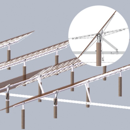
Conceptual second-axis dependency map. Project designers and adopted documents control actual geometry, loads, motions, acceptance criteria and safe states.
Name both axes and their reference frames. An azimuth–elevation arrangement, tilt–roll arrangement or another mechanism can create different support, drive and cable behavior. Define commanded and physical angle ranges, rate and acceleration assumptions where relevant, hard and software limits, backlash or compliance treatment, reference/calibration state and the sequence used to move between operating, parked, maintenance and protective positions. No values are implied here.
Map the swept volume of modules, frames, drive arms, counterweights, cable loops and access equipment. Test adjacent tracker clearance, ground and vegetation clearance, fence/building or equipment conflict, drainage and grading changes, maintenance approach and any crane or lifting envelope. Include construction and partially assembled states when they affect interference or stability.
Treat the cable path as moving geometry, not a late electrical detail. Define which conductors, harnesses, hoses or communication links cross each rotating interface; the permitted movement; support and strain-relief concept; connector location; bend/twist and abrasion evidence; drainage; protection; inspection access; and replaceable section. The electrical designer and tracker designer must share the same orientation and cycle envelope.
Trace Every Orientation into Structure and Foundation
The structure sees more than one operating pose. Create a state inventory that joins orientation, environmental action, drive/control condition, support assumptions and required check. Relevant states may include normal tracking, parked or stowed, motion between positions, one-axis-disabled, loss of power, maintenance, installation and site-specific snow, wind, seismic or accidental conditions. The responsible designers determine which states and combinations govern.
Trace each state from modules and supporting frame through both rotational interfaces, bearings and drives, pedestal or support frame, base connection, anchors and foundation into the ground. Record coordinate systems, signs, reference points and simultaneous action components. A maximum overturning moment detached from its associated shear, axial force, orientation and limit state is not a complete foundation input.
Check deformation and movement interfaces as well as resistance. Tracking accuracy, module clearances, bearing alignment, gear or actuator load, cable movement and control feedback can depend on structural rotation or flexibility. The project may need compatible stiffness information between tracker, pedestal and foundation; one scalar “capacity” does not describe that interaction.
Foundation layout and ground variability feed back into the motion system. Coordinate support position, elevation, inclination, settlement/rotation criteria, drainage and erosion context, ground-zone assignment, installation tolerance and as-built survey. If the foundation or pedestal changes, recheck the axis geometry, control references, cable route and energy/layout model—not only the base calculation.
The existing tracker wind and stow guide covers protective-state coordination in detail. For the second-axis concept decision, require an approved route that links the adopted environmental basis to commanded position, sensing, communication, backup power where specified, structural response, verification and recovery. Do not invent a universal wind trigger or assume that one “flat” pose is safest for every architecture and direction.
Integrate Drives, Sensors, Controls and Cabling as One System
A second drive does not simply duplicate the first. The two axes can share loads, power, commands, sensors, limits and safe-state logic. Their order of movement can change collision clearance, cable twist, structural demand and recovery behavior. Define the complete functional architecture before qualifying components.
The architecture should identify each drive and transmission, bearings, brakes or holding devices where used, position feedback, end/limit detection, sun or time-based inputs, weather inputs, local controller, plant-level controller, power supply, communications, manual/local operation, protection, alarms, data storage and command authority. Show what is common and what is independent between axes. Identify which state remains possible after the loss or disagreement of each input.
IEC 62817:2014+A1:2017 is an official design-qualification standard for solar trackers. Its public scope covers test procedures for key components and the complete system, parameters reported on a tracker specification sheet and selected pass/fail tests. This supports a critical evidence boundary: a qualified component is not automatically a qualified two-axis system, and a qualified system does not automatically prove fit for one site, foundation, layout or financial model.
Coordinate software and configuration as controlled product information. Record control version, parameter set, axis calibration, limit definitions, time/location source, command hierarchy, alarm mapping and change authority. Define how a replacement controller, sensor, drive or firmware revision is checked before returning the unit to service. This is configuration control, not a recommendation for a specific control algorithm.
Electrical interfaces must cover normal and abnormal motion. Reconcile moving DC/AC/data circuits, grounding/bonding strategy, isolation, connector and junction locations, cable protection, electromagnetic or communication compatibility requirements selected by the project, emergency/local controls and the documentation needed by installers and maintainers. Qualified electrical and controls personnel must complete the design under the applicable standards and law.
Price Failure States and Maintainability into the Case
The investment case should model services delivered by the whole tracker, not the catalog reliability of one motor. A two-axis unit may continue in a degraded orientation after one fault, move to a defined state, require local intervention or become unavailable. The architecture and site conditions determine the consequence.
Use a failure/value ledger before assigning availability or operating cost.
| State or event | Questions to close | Value/model input | Responsible evidence owner |
|---|---|---|---|
| one axis unavailable or position uncertain | permitted degraded position, isolation, structural acceptability, energy treatment and recovery route | affected capacity, duration distribution, restart and service cost | controls, structural and O&M leads |
| power, communication or weather-input loss | command authority, retained sensing, defined response, backup/return behavior and event record | common-cause exposure, downtime and auxiliary-system cost | electrical/control owner |
| sensor disagreement, limit or calibration fault | detection, voting or validation approach, stop condition, manual check and re-calibration evidence | false-trip/misposition scenario and service demand | control and commissioning owner |
| cable, connector, bearing, drive or brake condition | detection, access, isolation, replacement method, dependent damage and proof after repair | spares, labor/equipment, lead time and lost production scenario | mechanical/electrical/O&M owner |
| environmental or access restriction | safe position, storm/snow/temperature or site-access assumption, inspection trigger and restart authority | event frequency, restricted access window and recovery cost | project design and site O&M owner |
| planned inspection or maintenance | tasks, interval basis, staffing, tools, access, outage grouping and record | scheduled downtime and lifecycle resource plan | manufacturer evidence plus asset owner |
Do not populate the ledger with generic failure rates or maintenance intervals. Obtain applicable field data, qualification evidence, supplier instructions and owner assumptions, then state confidence and sensitivity. Distinguish independent unit events from common-cause events involving shared power, communication, weather sensing, software, access or spare parts.
Maintainability is a design input. Verify access at relevant orientations, working space, isolation, fall and lifting arrangements, replaceable-unit mass and route, specialist tools, calibration equipment, lubrication or adjustment tasks where specified, consumables, spare strategy and technical-document availability. The site safety plan, manufacturer instructions and applicable law control the actual work.
Return the result to the business model. Include planned and unplanned outage, degradation of one axis, service labor and equipment, spares and replacements, auxiliary energy, remote/local response, training, software/configuration support and end-of-life or residual assumptions selected by the owner. Run the cases that could change the concept decision rather than hiding them in one average operating-cost percentage.
Release the Concept Through Evidence Gates
Separate four questions: Can the model justify studying the second axis? Is the selected design qualified for its claims? Is it compatible with this site and project? Was the installed system commissioned and monitored as intended? Evidence from one gate cannot answer all four.
| Evidence gate | Required decision proof | What it does not establish alone | Hold condition |
|---|---|---|---|
| matched concept model | controlled baseline, candidate architecture, time-series delta, loss/cost/value assumptions and sensitivities | product qualification or buildability | value changes sign under unresolved material assumptions |
| architecture and project interface | motion envelope, state/load matrix, structure/foundation, controls/electrical, cable, access and failure responsibilities | manufacturing conformance or site commissioning | one added dependency lacks owner, design input or verification route |
| product/system qualification | applicable IEC 62817 or other adopted evidence, tested configuration, reported parameters, deviations and validity | site-specific energy, wind/foundation adequacy or lifetime | claim/configuration cannot be mapped to evidence |
| installation and commissioning | approved drawings/configuration, as-built geometry, axis calibration, functional and protective tests, punch/deviation closure and handover | future availability or long-term energy value | site state differs from the released design or open condition affects safe use |
| operational monitoring and maintenance | governed sensors/data, availability and event definitions, tracking-state records, performance comparison, inspections, interventions and changes | retroactive proof of an invalid design basis | data cannot distinguish resource, electrical, curtailment and tracker effects |
IEC 62446-1:2016 with Amendment 1:2018 defines public scope for grid-connected PV documentation, commissioning tests and inspection. IEC 61724-1:2021 covers PV performance-monitoring terminology, equipment and methods. Both official pages show stability dates in 2026, so confirm current status and project adoption. Neither public scope is a ready-made dual-axis acceptance checklist.
Define operational data before commissioning. The project should distinguish commanded and measured axis positions, operating/protective/fault state, availability and exclusion codes, weather/resource inputs, auxiliary energy, maintenance events, configuration changes and curtailment or electrical limitations at a level appropriate to the decision. Without state data, an energy variance may be attributed to the tracker when the cause is resource, shading, electrical availability, grid action or a different baseline.
Use the same Second-Axis Evidence Ledger through every gate. Update each claim, obligation, owner, document/configuration, status, exception and next decision. Release the concept only for its named stage: feasibility study, supplier inquiry, detailed design, procurement, installation or operation. A study approval is not permission to order hardware, and a commissioned unit is not a universal performance guarantee.
Next Step: Issue the Second-Axis Evidence Ledger
Create one row for every benefit claimed from the second axis and every dependency it adds. Record the matched baseline, evidence source, configuration, owner, status, sensitivity, due date and stop condition. Start with resource/value modeling, self-shading and motion limits, structural/foundation states, moving cables, controls and safe responses, maintainability, qualification, commissioning and monitoring. If a row cannot be mapped to a project decision, remove it; if it can change the winner, keep it visible.
For a supplier-scope discussion, send the site and decision stage, controlled baseline and two-axis model, module/array architecture, layout, motion and action basis, foundation/interface information, drive/control/electrical concept, lifecycle assumptions and available qualification/commissioning evidence. East Baoyu can confirm whether an available supplier-side tracking or steelwork scope matches the request and identify missing inputs within an agreed boundary. This does not predict energy, approve design or promise product availability, cost or performance. Contact info@baolaipipes.com with the exact concept decision.
Related Resources
- Solar Tracking Bracket — commercial parent for available tracking-system scope and project inquiry.
- Fixed versus Tracking PV — compare complete buildable mounting concepts on a matched energy and lifecycle basis.
- Solar Tracker Wind Load and Stow Strategy — coordinate protective states, sensing, structure and commissioning.
- Solar Tracker Slew Drive — verify a selected drive's mechanical, control and evidence interfaces.
- Solar Tracker Installation — qualify reference rows, production replication and handover.
References
- International Electrotechnical Commission. IEC 62817:2014+A1:2017, Photovoltaic systems—Design qualification of solar trackers. Official page checked 2026-08-24; stability date 2028.
- National Renewable Energy Laboratory. System Advisor Model Help—PV System: Orientation and Tracking. Accessed 2026-08-24.
- International Electrotechnical Commission. IEC 61724-1:2021, Photovoltaic system performance—Monitoring. Official page checked 2026-08-24; confirm lifecycle and project adoption.
- International Electrotechnical Commission. IEC 62446-1:2016, Documentation, commissioning tests and inspection, with Amendment 1:2018 available. Official page checked 2026-08-24; confirm lifecycle and project adoption.
References, disclosure and change record
References and further verification
- https://eastbaoyu.com/solar-tracker-wind-load-and-stow-strategy/
- https://webstore.iec.ch/en/publication/61127
- https://webstore.iec.ch/en/publication/24057
- https://webstore.iec.ch/en/publication/65561
- https://eastbaoyu.com/solar-mounting/solar-tracking-bracket/
- https://eastbaoyu.com/fixed-versus-tracking-pv-energy-comparison/
- https://eastbaoyu.com/solar-tracker-slew-drive/
- https://eastbaoyu.com/solar-tracker-installation/
Disclosure: East Baoyu manufactures and supplies products discussed on this website. Structured drafting tools may assist research and editing, but technical claims, project inputs and release decisions require qualified review under the applicable project responsibilities.
Version 1.0: Scheduled in the East Baoyu 30-article engineering knowledge-base batch on 2026-08-25.
View the public Content Change Log · Corrections: info@baolaipipes.com