

Authorship, review and evidence boundary
- Technical review
- East Baoyu Engineering Editorial Team
- Reviewed
- 2026-08-24
- Scope
- General engineering and procurement guidance. This article is not a project-specific design, capacity statement, certificate, warranty, code interpretation or contract requirement.
Evidence basis: Official and public references identified in the article. Project values and release decisions require qualified review under the applicable project responsibilities.
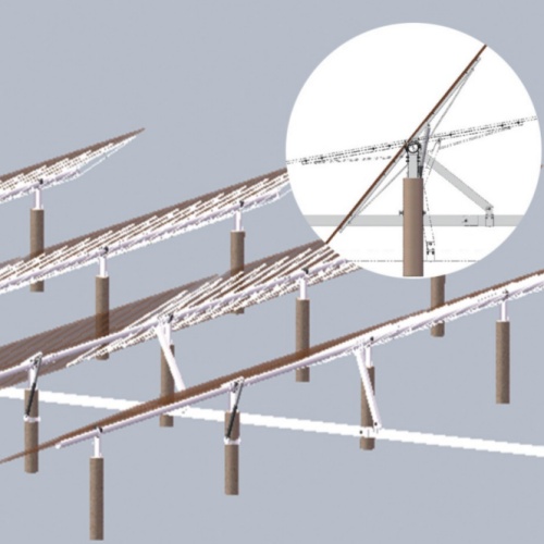
Read the Editorial PolicyA solar tracker torque tube should be specified as the longitudinal load path of a defined row, not selected from diameter, wall thickness and steel grade in isolation. The section must work with the row geometry, module mass and inertia, support spacing, bearings, drive arrangement, splices, attachments, design states, durability basis and manufacturable tolerances. The project structural and dynamic model sets those requirements. This guide shows how to turn that approved basis into a comparable RFQ and a traceable verification package; it does not provide a universal tube size, span, torque, wind limit, coating or acceptance tolerance, and it does not replace project wind, structural, foundation or drive engineering.
Treat the Tube as the Row's Longitudinal Load Path
The torque tube is often shown as one line, but the physical load path is a chain: module attachments, tube segments, splices, bearings, supports, drives and any stops or dampers. An individually acceptable tube can still be incompatible with the row when a joint changes stiffness, a bracket introduces eccentricity or segment errors accumulate. The relevant question is not “Which tube is strongest?” but “Which controlled chain reproduces the approved row model?”
Use a load-path map before writing the component specification.
| Row action or state | How it enters the tube chain | Response or interface to control | Evidence needed downstream |
|---|---|---|---|
| gravity, module weight and project-defined environmental actions | module attachment, rail or purlin connection | global bending, local attachment effects, support reactions and service clearances | approved model reference, interface drawing and calculation trace |
| aerodynamic mean, fluctuating and project-defined dynamic actions | distributed module pressure and eccentric module geometry | torsion, bending–torsion interaction, rotation, deformation and dynamic response | applicable wind/dynamic basis, model assumptions and configuration-specific review |
| tracking, braking, holding and emergency states | drive, brake, damper, stop or restraint interface | torque transfer, local load introduction, backlash or movement boundary and load sharing | drive-interface load table, connection definition and responsible-engineer approval |
| support, bearing and foundation behavior | bearing locations, restraint directions and support movement | span behavior, alignment, reactions and accumulated geometric error | support/bearing schedule, boundary-condition drawing and survey basis |
| fabrication, transport, assembly and service intervention | lifting points, temporary supports, joints and maintenance restraints | temporary bending/torsion, distortion, coating damage and changed boundary conditions | handling plan, assembly method, inspection points and permitted temporary states |
Research reinforces the system view without supplying a catalogue answer. A three-dimensional wind-tunnel benchmark for a single-axis tracker defines a complete aeroelastic row so that aerodynamic and structural behavior can be reproduced; it treats geometry, kinematics and dynamics together (Journal of Wind Engineering and Industrial Aerodynamics, 2024). Another study examines how tracker inertia, aspect ratio and torque-tube stiffness interact in torsional galloping (Engineering Structures, 2021). These findings do not justify transferring a section or numerical result to another project. They explain why the row configuration and its model must travel with the tube requirement.
Define ownership at the boundary. The tracker engineer owns the system model; component suppliers own assigned material, geometry, process and inspection evidence; the integrator closes interfaces. Omitting inputs from a component RFQ should not silently transfer system-design responsibility.
Freeze the Row Model Before Selecting a Section
Section selection should start only after the design basis is controlled enough for offers to mean the same thing. A row length without support locations is incomplete. A torque value without its state, application point, load combination and sharing assumption is ambiguous. A deflection limit without a datum and operating condition cannot be inspected. A material grade without its product form, governing specification and required properties may not match the calculation.
Freeze the states that can govern the tube or an interface: applicable tracking, parked/stow, drive/brake, loss-of-power, maintenance, lifting and environmental combinations. The approved project basis defines the real set; this list creates no new load case.
Then connect every analysis input to a purchasable or verifiable output.
| Input group | Project information to freeze | Why the tube decision depends on it | Controlled output |
|---|---|---|---|
| row geometry and segmentation | module arrangement, row length, tube axis, segment lengths, support and splice positions, overhangs and transport limits | sets spans, accumulated interfaces, local discontinuities and handling states | general arrangement, segment schedule and configuration IDs |
| mass, inertia and attachments | module/rail/purlin mass, mass distribution, eccentricity, attachment pitch and local geometry | affects static response, drive demand and dynamic representation | controlled mass-property basis and attachment drawing |
| actions and design states | project load cases, combinations, dynamic method, drive/holding actions, temporary states and service criteria | defines strength, stiffness, movement and interaction checks | calculation input sheet with source, units and revision |
| supports, bearings and drive | restraint directions, stiffness assumptions, clearances, friction or movement model, load sharing and local connection geometry | controls reactions, span response, alignment and load introduction | interface-control drawings and boundary-condition schedule |
| material and durability | product specification, required properties, environment, coating or corrosion route, drainage and compatible materials | changes section properties, fabrication route, inspection and service exposure | material/process/coating specification |
| manufacturing and verification | datums, measurable dimensions, hole/weld details, straightness/twist/runout definitions, sampling, trial assembly and record format | determines whether the modeled geometry can be repeatedly produced and proven | drawing tolerances, ITP and evidence matrix |
Keep the difference between qualification and project design explicit. IEC 62817:2014+AMD1:2017 addresses design qualification of solar trackers and includes tests of key components and the complete system. The official record describes both measured/reporting requirements and pass/fail criteria. It does not provide the project row model used to select this tube.
The boundary is even clearer in the official scope for UL 3703. The standard covers tracker and attachment safety matters, while its public scope excludes mechanical and structural integrity under wind, seismic and uplift loading and the base-to-platform connection. Confirm the current editions, amendments, national adoptions and contractual hierarchy for the actual project. A qualification mark or report should be read for its tested configuration and claim scope, not treated as a substitute for project-specific structural, wind or foundation engineering.
Issue the input sheet with a revision and exception route. A different span, drive location, module mass, support stiffness, material property or fabrication detail is a technical deviation, not merely a price option.
Control Segmentation and Interface Stack-Up
A long tracker row is assembled from shorter manufactured and transported items. Segmentation therefore affects more than logistics. It defines how many splices exist, where stiffness changes occur, how tolerances accumulate, where coatings or local details may be disturbed and which subassembly can be verified before dispatch.
Create a controlled interface list covering splices, bearings, drive connections, module/rail/purlin attachments, assigned dampers, stops, end details and any feature that modifies the tube. Give each interface one ID across the model, drawings, bill of materials, inspection plan and assembly record.
Avoid tolerance statements that cannot be reproduced. “Straight” is not an inspection method. A useful requirement names the datum, support condition, measurement span, orientation, temperature or stabilization condition where relevant, instrument or method, reporting resolution, sampling rule and acceptance authority. The same discipline applies to twist, runout, hole position, end squareness, splice fit and assembled-axis alignment.
| Interface | Definition to release | Stack-up or failure question | Representative evidence |
|---|---|---|---|
| tube segment to splice | section orientation, engagement, fasteners or welds, datum, hole pattern, gaps and surface/coating condition | does the joint reproduce assumed strength, stiffness, alignment and slip behavior through repeated segments? | controlled drawing, calculation reference, dimensional record and representative assembly |
| tube to bearing/support | axis and elevation datum, bearing position, restraint/movement directions, bracket geometry and clearance | can accumulated tube and support variation create forced fit, binding, eccentricity or lost movement? | interface drawing, gauge or survey record and installed-clearance check |
| tube to drive | torque and reaction application points, alignment, connection geometry, local reinforcement and permitted movement | does the local load path match drive and row models without unintended restraint or misalignment? | signed interface load table, mating drawing and trial-fit/inspection record |
| tube to module/rail/purlin | attachment pitch, orientation, clamp or fastener detail, hole/slot limits and module clearance envelope | does local detailing weaken, distort or rotate the tube or conflict with module movement and tolerance? | approved attachment drawing, first-article dimensions and representative fit |
| segment ends and accumulated row axis | cut/end geometry, indexing, seam or feature orientation, segment identity and assembled datum | will individually accepted parts assemble into the required row axis without selective matching or field forcing? | segment map, end checks and multi-segment trial assembly |
Place splices and local features according to the approved analysis, not a universal “best” location. Explicitly close any gap between a continuous-member model and discrete production joints. Review evidence applicability when a segment, bracket, adapter, hole/weld detail, material source, coating route or supplier changes.
Convert Structural Requirements Into Manufacturing Controls
An analysis result becomes useful to procurement only when it is linked to controlled product characteristics. The drawing and specification should identify the section shape and dimensions used in the calculation, governing material/product requirements, required properties and their direction where relevant, segment and feature geometry, permitted fabrication routes, connection details, surface protection, marking, inspection and records.
Nominal dimensions do not alone establish section properties. The project calculation and drawing must address permitted variation and any formed corner, seam, weld, hole, slot, cutout or reinforcement that changes the load path.
Make the manufacturing variables visible:
- identify the material specification, grade, product form, required properties and traceability;
- define section dimensions and tolerances with an inspection method and the calculation convention they support;
- control seam, weld, hole, slot and reinforcement locations relative to a stable section datum;
- route welding qualification, inspection and repair through the applicable project and governing standards;
- define the project corrosion-protection and repair route, then reconcile process effects with mating features and assembly clearance;
- mark segments so orientation, row position, batch, drawing revision and inspection record remain traceable;
- define lifting, stacking, dunnage, restraint and transport controls needed to preserve geometry and surface condition.
Do not publish a universal straightness, twist, wall, grade or coating target. The correct value is the one justified by the approved row response, interface clearance, process capability, applicable product rule, transport/assembly method and inspection uncertainty. A tighter number is not automatically safer if it is undefined, unmeasurable or disconnected from the model. A looser number is not acceptable merely because each individual part can be assembled.
Match evidence to its claim. A material certificate does not prove assembled-row alignment; a dimensional report does not prove torsional stiffness unless that relationship is established; a weld qualification does not approve an unreviewed joint geometry. Attach every record to the configuration, batch or process it can substantiate.
Verify a Representative Torque-Tube Chain
Choose a chain with the actual segment and orientation, a production splice, bearing/support, drive and module attachment. It should represent the released row basis, manufacturing route, supplier and inspection method. Materially different families may need separate verification configurations.
| Evidence level | What it can establish | Release question | Typical limitation to record |
|---|---|---|---|
| controlled design and document review | inputs, revisions, responsibilities, calculation/drawing consistency and approved deviations | is the offered configuration the same one the project has evaluated? | does not prove manufactured condition |
| material and process evidence | material identity, required test results, qualified processes, personnel and inspection status within stated scope | were controlled inputs and processes used for the identified items? | does not prove every dimension or assembled behavior |
| dimensional and visual inspection | section, features, datums, orientation, surface condition and traceable segment identity | do the manufactured parts match measurable drawing requirements? | sampling and instrument uncertainty limit the claim |
| interface and multi-segment trial assembly | fit, accumulated alignment, access, clearances, orientation and repeatable assembly method | can representative segments and mating parts form the intended chain without forcing or undocumented selection? | not a substitute for project structural/dynamic validation |
| configuration-specific qualification or test | the stated behavior of the tested specimen under defined boundary, loading and acceptance conditions | does the test answer the exact design question for an applicable configuration? | results do not automatically transfer across geometry, stiffness, mass, boundary or process changes |
| installed-row and handover records | as-built identity, alignment, interfaces, deviations and commissioning baseline | was the released chain correctly integrated at its real location? | site evidence remains project- and location-specific |
The evidence plan should name review points, responsibility, sampling, instrument/calibration requirements, acceptance criteria, nonconformance route and shipment records. Preserve raw results, units, locations, relevant conditions and the drawing link; a bare pass/fail label is weak evidence.
Wind-response research also cautions against treating one isolated configuration as universal. Experimental work on single-axis tracker arrays reports that wind direction, tracker tilt and row interactions affect load behavior (Renewable Energy, 2023). The useful procurement lesson is to retain the exact configuration and boundary of a test or analysis. Do not transfer a coefficient, critical speed or acceptance result from a different array, row geometry, stiffness, mass, support condition or test method without accountable engineering justification.
Define revalidation triggers before production. Review evidence applicability when the section, material, segment map, splice, bearing, drive/module interface, fabrication route, coating process, supplier or acceptance method changes. Record any decision to reuse evidence with its scope and owner.
Issue a Comparable RFQ and Release Basis
A useful torque-tube RFQ makes technical differences visible. Include configuration IDs, document hierarchy, model references, design states and assigned actions, segmentation, material/durability basis, interfaces, datum-based tolerances, fabrication restrictions, ITP, trial assembly, marking/packaging, submittals, deviations and acceptance authority.
Require assumptions and exceptions in a common schedule. Ask bidders to identify the offered section/properties, material and process route, segments/splices, interface changes, measurable tolerances, sampling, trial assembly, deliverables and missing inputs. A blank exception column is not proof that every model boundary was understood.
Before technical release, reconcile five questions:
- Does the offer represent the same row states, geometry, mass, supports, drive locations and interface loads as the approved basis?
- Are section properties, material properties, local details and joint representations traceable to the project calculations?
- Can every critical drawing characteristic be manufactured and measured with a named datum, method and acceptance rule?
- Does the evidence plan support the complete claim—from material and process through the representative chain—without relying on an unrelated certificate or test?
- Are deviations, design responsibilities, approval points and change triggers visible before purchase order release?
State what is approved and what remains conditional. Keep design acceptance, manufacturing release, first-article approval, production authorization, shipment release and site acceptance distinct.
Next Step: Submit the Row Basis
Send the row configuration, module mass and geometry, approved design states and calculation references, support/bearing/drive layout, segmentation and interface drawings, material/durability basis, proposed tolerances, evidence matrix and open exceptions to info@baolaipipes.com.
East Baoyu can review input completeness, manufacturability, component traceability, interface definitions and the proposed supplier evidence package within an agreed scope. The project's appointed structural, dynamic, wind, foundation and drive engineers retain responsibility for design methods, loads, acceptance criteria and final approval. If the tracker configuration or commercial supply boundary is still open, begin with the Solar Tracking Bracket page. If the drive boundary is unresolved, use the Solar Tracker Slew Drive guide before freezing the tube-to-drive interface.
Related Resources
- Solar Tracker Wind Load and Stow Strategy — establish the project wind, operating and protective-state basis before converting actions into tube requirements.
- Solar Tracker Installation — use the released configuration and evidence package to control reference-row assembly and site replication.
- Module Datasheet Inputs Needed for Solar Mounting Design — control the module geometry, mass and interface inputs that enter the tracker row model.
References
- IEC. IEC 62817:2014+AMD1:2017 CSV — Photovoltaic systems: Design qualification of solar trackers. Confirm current edition, amendments, national adoption and project applicability.
- UL Standards & Engagement. UL 3703 — Solar Trackers. Consult the official scope and confirm project applicability.
- Rodríguez-Casado et al. Experimental Benchmark for the 3D wind tunnel testing of torsional aeroelastic instabilities in single-axis solar trackers. Journal of Wind Engineering and Industrial Aerodynamics, 253 (2024), 105838.
- Martínez-García et al. Influence of inertia and aspect ratio on the torsional galloping of single-axis solar trackers. Engineering Structures, 243 (2021), 112682.
- Ma et al. Experimental investigations on the wind load interference effects of single-axis solar tracker arrays. Renewable Energy, 202 (2023), 566–580.
References, disclosure and change record
References and further verification
- https://doi.org/10.1016/j.jweia.2024.105838
- https://doi.org/10.1016/j.engstruct.2021.112682
- https://webstore.iec.ch/en/publication/61127
- https://www.shopulstandards.com/ProductDetail.aspx?UniqueKey=30148
- https://doi.org/10.1016/j.renene.2022.11.112
- https://eastbaoyu.com/solar-mounting/solar-tracking-bracket/
- https://eastbaoyu.com/solar-tracker-slew-drive/
- https://eastbaoyu.com/solar-tracker-wind-load-and-stow-strategy/
- https://eastbaoyu.com/solar-tracker-installation/
- https://eastbaoyu.com/module-datasheet-inputs-needed-solar-mounting-design/
Disclosure: East Baoyu manufactures and supplies products discussed on this website. Structured drafting tools may assist research and editing, but technical claims, project inputs and release decisions require qualified review under the applicable project responsibilities.
Version 1.0: Scheduled in the East Baoyu 30-article engineering knowledge-base batch on 2026-08-25.
View the public Content Change Log · Corrections: info@baolaipipes.com