Solar Mounting Systems
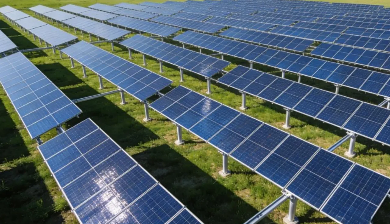
Screw piles can be a candidate foundation for ground-mounted photovoltaic arrays where loads, soil conditions, access, corrosion exposure, installation controls and testing are suitable.


Steel screw foundations for suitable ground conditions, with pile geometry, material, corrosion protection, installation criteria and testing confirmed from project loads and site data.
Screw piles can provide a practical ground-anchoring route for solar, light construction, fencing, signage and temporary structures when the loads, soil, access, corrosion exposure and installation controls are suitable.
For suitable ground and access conditions, screw piles can reduce excavation, spoil and concrete curing activities. Capacity, corrosion protection and acceptance criteria still require project-specific verification.
Request Pricing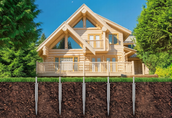
Use this template to define a project-specific pile schedule. Dimensions shown in a catalog are indicative until the reactions, ground, durability and connection requirements have been reviewed.
| Parameter | Published value status |
|---|---|
| Shaft type and diameter | By approved pile schedule |
| Wall / bar thickness | By structural and durability design |
| Length and extensions | By ground profile and installation criteria |
| Helix geometry | By load-transfer design |
| Material grade | By drawing and material specification |
| Head / coupling detail | By supported-system interface |
| Corrosion protection | By exposure and design life |
| Installation / test criteria | By approved method statement and test plan |
Catalog dimensions and website examples are selection inputs only. The approved drawing, calculation, quotation, ITP and contract define the supplied product.
Request project data sheetFollow-on work can begin after installation acceptance without concrete curing
Material, sacrificial thickness and coating selected for the site exposure and design life
Compression, uplift and lateral criteria confirmed by design and the agreed test plan
Excavation and spoil can be reduced where ground conditions permit direct installation
 01
01Ground screw piles for utility-scale PV arrays with fast grid installation and reliable pull-out resistance.
View Details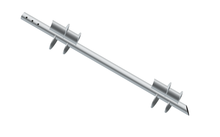 02
02Clean and accurate footings for solar carports, canopies and light steel structures.
View Details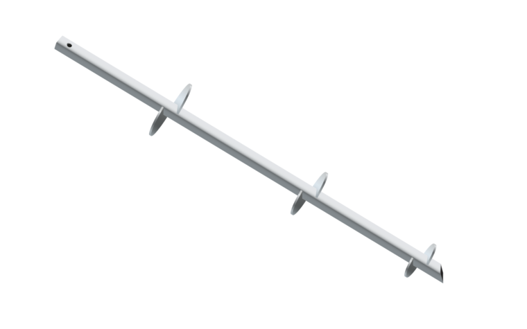 03
03Dependable anchoring for fences, signage, barriers and temporary works without concrete.
View Details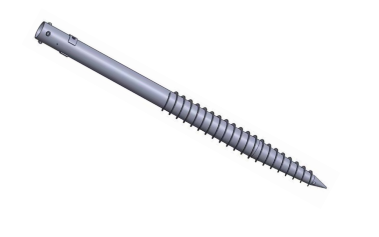 04
04Foundation options that may support later removal where the design and ground conditions permit.
View Details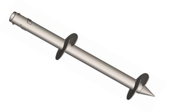 05
05Low-disturbance pile foundations for decks, walkways and sensitive terrain.
View Details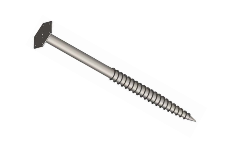 06
06Fast steel screw foundations for cabins, modular units and small structures.
View DetailsScrew piles can be a candidate foundation for ground-mounted photovoltaic arrays where loads, soil conditions, access, corrosion exposure, installation controls and testing are suitable.

For decks, gazebos, cabins, fences and other light structures, pile geometry and acceptance criteria must be verified from the actual reactions and site information.
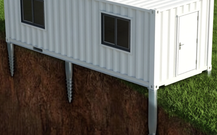
Temporary and modular projects may benefit from a reduced-wet-trade foundation route. Later removal or reuse depends on the design, site conditions, installation records and component condition.
We review loads, site data, installation method, standards, corrosion exposure and acceptance criteria, then identify assumptions and missing information.
The quotation and drawings define pile geometry, material, fabrication, coating, tolerances and the applicable inspection plan.
Inspection and release follow the agreed ITP and order scope; packing and export documents are coordinated for the destination and shipment route.
Installation remains the responsibility of the appointed site contractor. Available manuals and remote technical support are provided within the agreed supply scope.
Lead sections, Extensions and couplings, Heads and brackets, Anchor accessories
Solar farms · Carports and canopies · Fencing and signage · Temporary structures · Decking and boardwalks · Light buildings
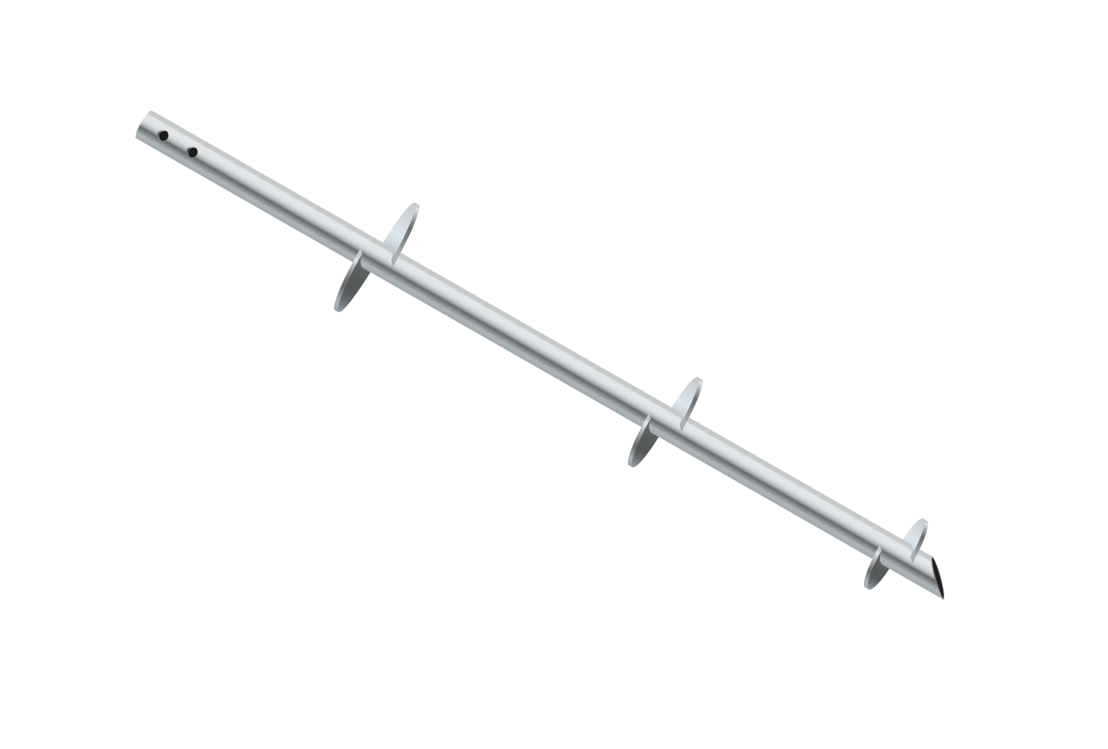
Catalog families cover round-pipe and square-bar lead sections, extensions, caps, brackets, adapters and anchor interfaces. Published catalog examples are not a project pile schedule.
Send the site conditions, reactions and layout. We will identify missing inputs and confirm the drawing, testing and quotation route.
Get a Quote