

Ground Screws for Temporary Structures
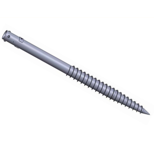
Purpose of this page. Temporary structures require a controlled installation and removal route; temporary duration does not make wind, crowd, uplift, stability or inspection demands optional. It explains the engineering and procurement route without treating a catalog example as an approved project model.
Application decision context
Event structures, temporary buildings, equipment, signage or works platforms can experience short-duration but severe actions. Reuse may be possible only when the pile, threads, couplings, heads and coating remain within defined inspection and acceptance limits.
Required project inputs
- Structure geometry, use period, occupancy and reactions
- Wind, ballast, uplift, crowd and accidental actions
- Ground profile, buried services and restoration constraints
- Installation equipment, access, programme and removal sequence
- Reuse inspection, identification and storage requirements
Configuration and interface route
Shaft, helix, length, head and adjustment follow the actual load and temporary structure interface. A removable connection should not introduce unapproved eccentricity or slip. Different event zones or ground conditions may need different schedules.
Manufacturing and verification plan
Installation acceptance can include depth, torque where project-approved, position, alignment and proof testing. Each reused pile needs identification and inspection criteria for deformation, wear, corrosion, threads, couplings and previous repairs. Reuse is a release decision, not an automatic property.
Installation, logistics and site coordination
The method covers service clearance, set-out, installation, temporary stability, handover, periodic checks, removal and restoration. Weather limits and change management are important where the structure configuration evolves during an event or temporary works stage.
Design and supply boundaries
- Temporary use does not reduce the need for design
- Reuse requires inspection and release criteria
- Removal can be limited by soil movement, damage or access
- Ground restoration and disposal responsibilities must be stated
Documents to define before release
- Temporary structure reaction and layout schedule
- Installation, handover and periodic-inspection plan
- Pile identification and reuse register
- Proof-test or acceptance record where required
- Removal and restoration method
- Damage, repair and final disposition log
The Product Data Center shows how this application connects to the product family and configuration route. Public catalogs support orientation only. The approved calculation, drawing, bill of material, quotation, ITP and contract define the supplied scope. Use the Evidence Center to request the records applicable to the actual order.
Technical data framework
Project-specificGround Screw Pile Technical Data Template
Use this template to define a project-specific pile schedule. Dimensions shown in a catalog are indicative until the reactions, ground, durability and connection requirements have been reviewed.
Required design inputs
- Compression, uplift, shear and moment reactions
- Geotechnical profile, groundwater, frost and obstructions
- Pile-head interface, tolerances and supported-system geometry
- Design life, soil/atmospheric corrosivity and inspection access
- Installation equipment, test locations and acceptance plan
Decision boundaries
- Not selected from soil description alone
- Installation torque is a control only where a project-specific relationship is approved
- Capacity requires design and the agreed verification method
- Coating and sacrificial thickness follow the exposure and design-life assessment
| Parameter | Published value status |
|---|---|
| Shaft type and diameter | By approved pile schedule |
| Wall / bar thickness | By structural and durability design |
| Length and extensions | By ground profile and installation criteria |
| Helix geometry | By load-transfer design |
| Material grade | By drawing and material specification |
| Head / coupling detail | By supported-system interface |
| Corrosion protection | By exposure and design life |
| Installation / test criteria | By approved method statement and test plan |
Project deliverables
- Approved pile schedule and interface drawing
- Material certificate and dimensional report
- Coating / galvanizing report where specified
- Installation record and exception log
- Proof / production test report where required
- Release documentation defined by the ITP
Acceptance rule
- Applicable standard and drawing revision identified
- Inspection characteristic, frequency and acceptance criteria defined
- Records linked to the actual batch, item or installation location
- Exceptions and release authority documented
Catalog dimensions and website examples are selection inputs only. The approved drawing, calculation, quotation, ITP and contract define the supplied product.
Request project data sheetStable information architecture
Open Product Data Center Product family → configuration → application → evidence
Configuration route
Lead sections, Extensions and couplings, Heads and brackets, Anchor accessories
Application pages
Solar farms · Carports and canopies · Fencing and signage · Temporary structures · Decking and boardwalks · Light buildings
Resources and evidence
Catalog families cover round-pipe and square-bar lead sections, extensions, caps, brackets, adapters and anchor interfaces. Published catalog examples are not a project pile schedule.