

Authorship, review and evidence boundary
- Technical review
- East Baoyu Engineering Editorial Team
- Reviewed
- 2026-09-05
- Scope
- General engineering and procurement guidance. This article is not a project-specific design, capacity statement, certificate, warranty, code interpretation or contract requirement.
Evidence basis: Official and public references identified in the article. Project values and release decisions require qualified review under the applicable project responsibilities.
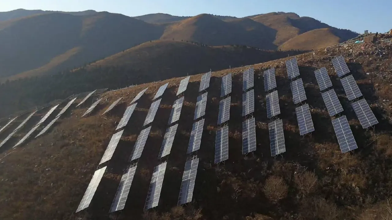
Read the Editorial PolicyA fixed-tilt ground-mount solar layout can fit the site boundary and still fail the terrain test. Rows may cross grade breaks, lose required clearance, interrupt drainage, multiply support variants or demand earthwork that was absent from the concept estimate. Before a racking family or civil quantity is released, divide the site into terrain zones and compare the permitted response in each one: retain existing ground, grade selectively, step or split tables, vary an approved support configuration, or exclude the area. The output is a Terrain Accommodation Register that links each zone to survey evidence, array geometry, civil work, foundation implications and approval status. This guide does not set universal slope, clearance, grading or structural limits.
Define the Terrain Decision Before Selecting the System
“Suitable for uneven terrain” is not a usable project requirement. It does not state the surface represented, direction of slope, grade break, permissible adjustment, clearance reference, drainage constraint or structural configuration. It also does not identify who decides when the standard table no longer applies.
At tender stage, define the decision as a bounded comparison:
For each terrain zone, which combination of array geometry, site work and approved mounting configuration produces a buildable layout without hiding drainage, foundation, access or energy consequences?
The primary decision owner is normally the party coordinating civil, structural, geotechnical, energy and construction inputs. Individual approvals remain with the professionals and authorities named by the project. A mounting supplier can state the proposed configuration envelope and supply interfaces, but it should not silently approve the survey, grading, drainage or foundation design.
Start with five candidate responses.
| Terrain response | What stays controlled | Evidence needed before selection | Common reason to reject or restrict it |
|---|---|---|---|
| Retain existing ground | Natural surface and drainage pattern remain the civil baseline | Controlled terrain model, row fit, clearances, access, vegetation and installation review | Standard geometry cannot cover local grade breaks or construction tolerances |
| Selective grading | Defined cuts, fills or local pads alter only identified zones | Grading surface, earthwork balance, drainage/erosion review, foundation and restoration implications | Earthwork creates unresolved water paths, fill conditions, access or permit effects |
| Step or split tables | Table segments change at controlled terrain transitions | Segment rules, row-end details, electrical/layout consequences, setting-out and packing logic | Fragmentation adds unpriced components, work fronts or unverified edge conditions |
| Vary support configuration | Approved post/head/brace variants absorb a defined range | Structural calculations, connection details, foundation inputs, tolerances and variant schedule | A field adjustment exceeds the released configuration or changes the load path |
| Exclude the zone | The area leaves the buildable array | Exclusion boundary, reason, capacity effect and interface with roads, drainage or setbacks | The retained layout no longer meets the project objective or creates new isolated rows |
This is not a ranking from best to worst. A project may preserve ground in one zone, grade a road crossing in another, step a row at a local break and exclude a drainage feature. The selected mix must use the same controlled survey and layout assumptions.
Divide the Site by Buildability, Not Contour Appearance
A terrain zone should contain locations that can use the same decision rule. A visually smooth contour plan can still combine different cross-slopes, grade breaks, ground conditions, drainage paths and access constraints. Conversely, two separated areas may use the same mounting configuration if their controlling conditions and evidence match.
Use the project’s controlled topographic model rather than tracing zones from a screenshot. The model should carry its coordinate reference, vertical datum, units, survey date, revision, breaklines, voids and known limitations. The separate guide to topographic survey requirements for ground-mount solar structures explains how to prepare that input. This article begins after a usable terrain model exists.
For zoning, examine at least:
- longitudinal and cross-slope along the proposed table orientation;
- ridges, toes, crests, banks, depressions and abrupt grade changes;
- existing and proposed drainage routes, channels, culverts and erosion-sensitive areas;
- roads, cable corridors, equipment pads, fences, utilities and construction access;
- minimum and maximum clearance locations under the project’s defined reference;
- foundation investigation points, fills, groundwater or obstruction information supplied by the geotechnical team;
- vegetation, agricultural, environmental or restoration requirements that constrain disturbance; and
- areas where survey confidence or coverage differs.
The U.S. Department of Energy describes large-scale solar siting as a process that considers topography together with land, zoning, wildlife, environmental, community and interconnection factors. That is a useful reminder that “structurally possible” is not the only site decision. Its guidance is U.S.-specific policy context, not a universal approval route (DOE large-scale solar siting).
Give every zone a stable ID and geometry. Record why the boundary exists. “North field” is not enough if only a narrow cross-slope band requires a different response. Keep uncertainty visible: a preliminary surface, an unverified fill boundary or an unsurveyed drainage feature should create an open or held condition rather than a precise-looking release.
Build a Terrain Envelope for Each Table Family
The terrain envelope describes where one defined table family may be used without an undocumented change. It is not a supplier brochure range. It is a project record that connects the approved system geometry to the surface and work method.
For each table family, define the inputs and limits that matter to the adopted design. These may include table orientation and length, tilt convention, support pattern, height or head variants, permitted connection adjustment, nominal clearance reference, installation tolerance and any restrictions at row ends or grade breaks. Values come from the project’s calculations, drawings, manuals and approval route. Do not copy a slope percentage or adjustment range from another project.
Then test the family against the terrain model row by row. Record the governing location rather than only an average slope. An average can conceal a short crest, depression or cross-fall that controls clearance, exposed post length, bracing geometry or installation access.
Use this Terrain Envelope Record for the comparison:
| Record field | Required entry | Gate question |
|---|---|---|
| Zone and source | Zone ID, coordinates/boundary, terrain-model revision and confidence/void note | Does the decision refer to the actual controlled surface? |
| Array geometry | Module/table family, tilt/azimuth convention, row direction, pitch and layout revision | Is the same geometry used by energy, civil and structural teams? |
| Governing terrain | Critical grade breaks, longitudinal/cross-slope locations and existing/proposed surface | Which location controls the response, and can it be inspected? |
| Clearance and access | Defined clearance reference, critical locations, construction and O&M access paths | Do all required clearances and access conditions remain within the released basis? |
| Mounting configuration | Support/head/brace/foundation variants and permitted adjustment source | Is every field variant represented by an approved detail and quantity? |
| Civil response | Retained ground, cut/fill, local pad, road or drainage work and surface-restoration basis | Has civil work been designed rather than treated as a supplier assumption? |
| Exceptions | Split/short table, row end, obstruction, excluded area or special work method | Does each exception have an owner, cost path and technical disposition? |
| Status | Open, hold, conditionally coordinated or released for a named use | What may proceed, and what event reopens the decision? |
The fixed-tilt solar mounting design article checks whether all project models agree. The Terrain Envelope Record has a narrower job: it establishes which terrain response and table family apply at each location before that wider release.
Compare Earthwork with the Consequences It Creates
Reducing steel variation can increase civil work. Reducing grading can increase table variants, setting-out effort or excluded area. The comparison should therefore measure consequences across the same site and layout, not compare one supplier’s hardware with another party’s incomplete civil allowance.
For each option, quantify or clearly mark as pending:
- cut, fill, haul, stockpile, disposal or imported material under the civil design;
- temporary and permanent access needed by survey, piling, assembly, lifting and maintenance;
- surface-water paths, drainage structures, erosion and sediment controls;
- changes to ground cover, soil compaction, restoration and vegetation management;
- foundation-zone changes caused by new grade, fill, scour exposure or construction disturbance;
- table, support, brace, fastener and foundation variants;
- short tables, row ends, electrical string/layout changes and unavailable land;
- installation cycles, survey/set-out points, quality records, packs and workfront breaks; and
- energy-model changes caused by row relocation, pitch, orientation, shading or exclusions.
NREL’s PV-SMaRT work identifies soil compaction, soil depth, ground cover and disconnection between arrays as important factors in stormwater analysis. Its modeling also accounts for climate, soil, vegetation, array spacing and slope. This does not select a drainage solution, but it shows why grading and row geometry should reach the civil and hydrologic model before the racking route is fixed (NREL PV-SMaRT).
The U.S. EPA’s construction stormwater resources treat land grading, construction sequencing, erosion control and runoff control as related planning topics. Applicable permits and approved local designs control the project. Use the EPA material as a prompt to include these interfaces, not as a substitute for the governing stormwater plan (EPA construction BMPs).
Do not claim “minimal grading” unless the comparison states the surface revisions and included work. A concept may omit road tie-ins, pile working platforms, drainage crossings or restoration. Those omissions can make a low earthwork number look more complete than it is.
Return Terrain Changes to Structure and Foundations
Terrain accommodation changes more than post height. It can change the relationship among module plane, supports, bracing, connection eccentricity, exposed length, foundation head, embedment, ground clearance and construction state. The responsible engineers must determine which effects are material under the governing design basis.
ASCE’s 2026 Design and Construction of Solar PV Structures covers ground-mounted systems, design loads, structural design, foundations, construction quality and commissioning. Its public chapter summaries state that installation tolerances should be supplied through project drawings and the racking manufacturer’s manual, and that structural performance should be shown through applicable calculations, testing or both. Apply the licensed manual and adopted requirements through the project’s professional route. The public summary does not provide a universal terrain envelope (ASCE MOP 162).
For each terrain response, ask the structural and foundation teams:
- Does the table family remain inside the analyzed geometry and boundary conditions?
- Does a longer or differently restrained support create a new member or connection case?
- Do grade changes alter exposed length, effective restraint, installation equipment or inspection access?
- Does cut or fill change the geotechnical model, surface stability, scour/erosion exposure or foundation test representation?
- Can a permitted field adjustment be measured and recorded, or does it require a revised detail?
- Which variant is represented by qualification, prototype, load test or first-table evidence, and where does that representation stop?
Use the fixed-tilt solar mounting foundation workflow to establish foundation zones and their test/production basis. A terrain-zone boundary and a foundation-zone boundary may differ. Keep both identifiers and map their intersection rather than forcing one label to carry two engineering decisions.
Make Variation Visible to Procurement and Construction
A terrain strategy is not complete when the layout looks buildable. It must reach the bill of materials, quotation, packing plan, installation drawings and field records. Otherwise, a designed variant becomes an informal site adjustment.
Create a controlled variant schedule. Each configuration mark should identify the table family, relevant support or connection variants, foundation route, permitted zone, quantities, drawing/model revision and inspection route. Link the schedule to the same zone IDs used in the Terrain Accommodation Register.
When comparing proposals, separate at least three quantities:
- standard repeated tables within the released terrain envelope;
- controlled variants such as stepped tables, short rows, altered supports or special ends; and
- civil, survey, foundation, access and restoration work that sits outside the hardware supply but affects the project decision.
The fixed-tilt solar mounting cost guide explains how to normalize table families, discontinuities and work packages. Use it after the terrain route is defined. A supplier should not be asked to hold a firm standard-table quantity while the project still allows either extensive grading or widespread configuration changes.
Construction documents should show how crews identify the applicable zone and configuration in the field. If the installed surface or support condition differs from the released basis, the response should be hold, record and disposition. “Adjust to suit” is not a complete instruction when the adjustment can change structure, clearance, drainage, foundations or quantities.
Prove One Representative Zone Before Repeating the Route
Before extending a terrain response across many rows, select a representative zone and reconcile the planned model with the field condition. This is not a universal requirement or a substitute for project inspections. It is a controlled way to test whether survey, setting-out, civil work, foundation installation and racking geometry use the same basis.
Choose a location that represents the decision being released. The easiest flat table will not verify a stepped transition or the upper end of an approved support range. Record why the zone is representative and what it does not cover.
| Release check | Evidence to review | Possible disposition |
|---|---|---|
| Source control | Survey control, terrain/grading revision, zone boundary and set-out file | Reconcile files or hold if field control cannot be traced |
| Ground and civil condition | Existing/proposed level, cut/fill state, drainage feature, access and restoration status | Accept for the named use, complete civil work or revise the zone |
| Foundation interface | Installed foundation identity, position/elevation, relevant records and approved head condition | Release, correct, test/escalate or redesign through the named authority |
| Table geometry | Configuration mark, support variants, tilt/row direction and critical clearances | Release only the represented configuration or revise the envelope |
| Construction method | Equipment access, assembly sequence, adjustment method and measurable tolerances | Update the approved method or limit the release |
| Downstream reconciliation | Layout, model, drawing, BOM, packing/workfront and inspection status | Release repeat work only after all affected outputs agree |
The final state should say exactly what may repeat: a named terrain response, table family, support/foundation combination, zone range, document revision and inspection route. It should also name the triggers that reopen the decision, such as a revised survey, changed grading, unexpected fill or obstruction, different module/table geometry, revised drainage, out-of-envelope support condition or field nonconformance.
Issue the Terrain Accommodation Register
The Terrain Accommodation Register is the handoff between early layout and a controlled design/procurement basis. Use one row for each zone–table-family intersection, not one row for the whole project.
| Register field | Minimum content |
|---|---|
| Identity | Project, zone, table family, configuration mark, coordinates/boundary and responsible coordinator |
| Source basis | Terrain model, grading surface, layout, drainage, geotechnical and design-basis revisions |
| Selected response | Retain ground, selective grading, step/split, support variation, exclusion or approved combination |
| Decision evidence | Governing locations, critical clearances, civil quantities/status, structural/foundation review and constructability evidence |
| Scope consequence | Standard/variant quantities, civil and installation work, exclusions, cost/schedule owner and procurement assumptions |
| Approval boundary | Technical owners, permitted downstream use, open conditions and required deliverables |
| Change triggers | Surface, layout, module, table, foundation, drainage, access or field events that require reassessment |
| Release status | Open, held, conditionally coordinated or released, with date and controlled revision |
Do not use the register to transfer design responsibility to a manufacturer or to convert pending information into an accepted value. Its purpose is to show how one project decision moves through several disciplines and commercial scopes.
Related Resources
- Fixed PV Bracket — define the project-specific fixed-mounting configuration and required inputs.
- Topographic Survey Requirements — prepare a controlled terrain model and survey package.
- Fixed-Tilt Solar Mounting Design — reconcile energy, civil, structural, foundation, drawing and BOM models.
- Fixed-Tilt Solar Mounting Foundation — divide the site by foundation evidence and release each route.
- Fixed-Tilt Solar Mounting Cost — normalize table families, discontinuities, scope and cost changes.
References
- American Society of Civil Engineers — Design and Construction of Solar PV Structures, MOP 162 (2026)
- National Renewable Energy Laboratory — Photovoltaic Stormwater Management Research and Testing
- U.S. Environmental Protection Agency — National Menu of Best Management Practices for Construction Stormwater
- U.S. Department of Energy — Large-Scale Solar Siting Research
Next Step: Release One Terrain Zone
Select one zone that contains a real terrain constraint. Issue the controlled survey surface, preliminary layout, table family, project load and clearance basis, civil/grading concept, drainage and access constraints, ground information, foundation route, quantity assumptions and open decisions. Complete one Terrain Accommodation Register row and trace it into the layout, structural/foundation review, drawing, BOM and field control. Do not release the same response across other zones until their evidence fits the stated envelope.
Submit the bounded package through Fixed PV Bracket when you need East Baoyu to define a proposed mounting configuration, variation schedule and supply-document scope for project review. The project’s appointed civil, structural, geotechnical, energy, environmental and construction parties retain their design, permitting, safety and release responsibilities.
References, disclosure and change record
References and further verification
- https://eastbaoyu.com/topographic-survey-requirements-ground-mount-solar-structures/
- https://www.energy.gov/cmei/systems/large-scale-solar-siting-research
- https://eastbaoyu.com/fixed-tilt-solar-mounting-design/
- https://www.epa.gov/npdes/national-menu-best-management-practices-bmps-stormwater-construction
- https://ascelibrary.org/doi/10.1061/9780784486849
- https://eastbaoyu.com/fixed-tilt-solar-mounting-foundation/
- https://eastbaoyu.com/fixed-tilt-solar-mounting-cost/
- https://eastbaoyu.com/solar-mounting/fixed-pv-bracket/
Disclosure: East Baoyu manufactures and supplies products discussed on this website. Structured drafting tools may assist research and editing, but technical claims, project inputs and release decisions require qualified review under the applicable project responsibilities.
Version 1.0: Scheduled as EB50-016 on 2026-09-05.
View the public Content Change Log · Corrections: info@baolaipipes.com