

Authorship, review and evidence boundary
- Technical review
- East Baoyu Engineering Editorial Team
- Reviewed
- 2026-09-06
- Scope
- General engineering and procurement guidance. This article is not a project-specific design, capacity statement, certificate, warranty, code interpretation or contract requirement.
Evidence basis: Official and public references identified in the article. Project values and release decisions require qualified review under the applicable project responsibilities.
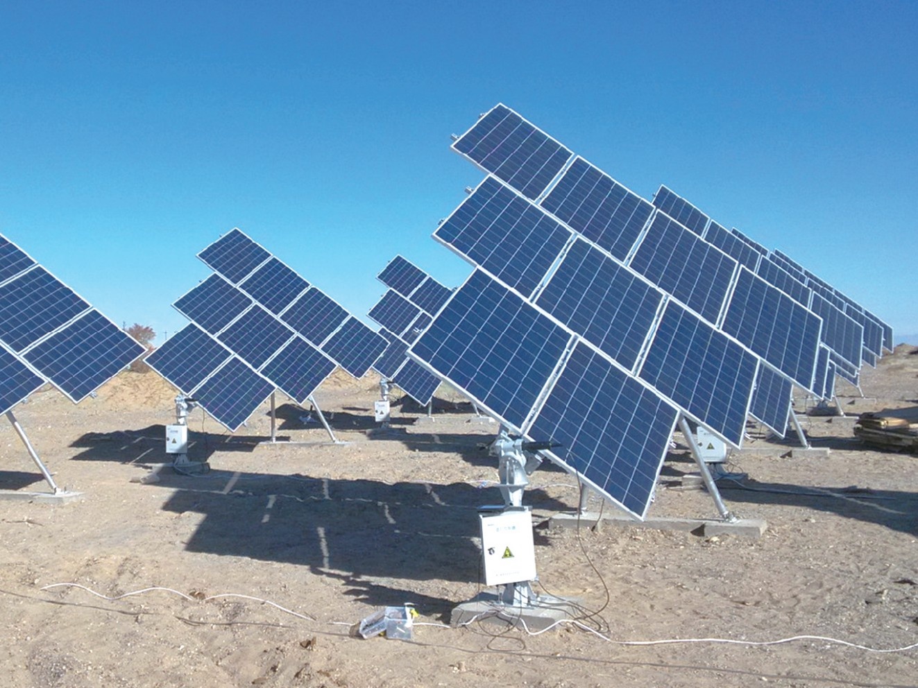
Read the Editorial PolicyWhen a solar tracking system row stops, reports the wrong angle, or remains in stow, a reset is not the first diagnosis. First preserve the commanded state, measured position, alarm sequence, weather state, power, communications, and visible condition. Then determine whether the symptom is isolated to one row or shared across a block, and test the least intrusive fault domains before allowing movement. The required output is not “tracker fixed”; it is a traceable decision to keep safe, inspect, test, reset, repair, or escalate, followed by defined return-to-service evidence. Site procedures, manufacturer instructions, electrical-safety rules, and the appointed operator govern every intervention.
Preserve the Incident Before Changing the State
A stopped or misaligned row is a symptom, not a cause. It may result from loss of auxiliary power, interrupted communications, a controller or configuration issue, a position-feedback problem, a drive fault, mechanical obstruction, structural movement, or a protective command that is working as intended. Changing the state too early can erase volatile evidence, move a row into an unsafe condition, or make a recurring common-cause fault look like an isolated nuisance.
The first response should establish an incident boundary. Identify the exact row or tracker ID, the first known abnormal time, the last known normal state, the command then in force, and who has operational authority. If the plant procedure requires an electrical or mechanical safe state, follow it before investigation. Do not approach, energize, release, jog, or reset equipment on the basis of this article.
Use a state-preservation card before any authorized intervention:
| Capture field | Minimum record | Why it matters |
|---|---|---|
| Asset identity | Plant, block, row, controller, drive and relevant firmware/configuration identifiers | Prevents evidence from being attached to the wrong configuration |
| Event chronology | Last normal timestamp, first alarm, subsequent alarms, command changes and operator actions | Separates initiating events from secondary alarms |
| Commanded and measured state | Requested mode/angle, reported mode/angle, local indicator where safely observable, and data quality flag | Defines the mismatch without assuming its cause |
| Operating context | Wind or other protective input, irradiance/time state, maintenance activity, grid or auxiliary-power event, and recent change | Tests whether the row is obeying protection or responding to an external condition |
| Data snapshot | Alarm codes, controller status, communication quality, power values and relevant trend window | Preserves evidence that a reset or reboot may change |
| Physical observation | Obstruction, unusual sound, heat, odor, deformation, loose parts, settlement, cable damage or water ingress, observed from an approved position | Identifies stop conditions and directs qualified inspection |
Photographs and screenshots need timestamps and asset IDs. Record missing or suspect telemetry as missing; do not convert an unavailable angle, stale tag, or communication timeout into a mechanical diagnosis.
Describe the Fault as a State Mismatch
Write the symptom in terms of expected, commanded, reported, and observed state. “Tracker failure” is too broad for a work order. A useful statement is closer to: “Row R-214 received the block tracking command at 09:42, its reported angle remained unchanged, the adjacent rows moved, and the local position has not yet been independently verified.” That statement supports tests without naming an unproved component failure.
Different mismatches suggest different starting checks, but none proves a root cause:
| Observable mismatch | First questions | Do not conclude yet |
|---|---|---|
| No telemetry from one row | Is row power present? Is the device reachable? Is the last value stale? Are neighboring devices on the same network path visible? | The drive is failed |
| Command acknowledged, angle unchanged | Is the measured position valid? Was motion inhibited? Is a protective state active? Is torque, current or travel-limit information available? | The actuator or gearbox must be replaced |
| Reported angle changes, field position appears wrong | Are the asset ID, sign convention, sensor reference, calibration and local indicator consistent? | The structure has moved or the sensor alone is defective |
| Several rows stop together | What power, communications, controller, weather input, configuration or upstream command do they share? | Multiple independent row failures occurred simultaneously |
| Row remains in stow | Is the stow command still asserted? Has the release condition been met? Are weather inputs valid and time-aligned? | The protection logic is malfunctioning |
| Repeated movement or oscillation | Is feedback stable? Are commands alternating? Is there obstruction, backlash, looseness or an unstable input? | A software change is the correct remedy |
The NREL-authored paper A Method for Estimating Time-Series PV Production Loss From Solar Tracking Failures explains why tracker stalls can be difficult to detect: unlike an outage that takes equipment fully offline, a stalled tracker may only partially reduce production. Its detection methods distinguish abnormal production behavior; they do not identify the physical root cause of a particular row. Use analytics to locate and prioritize a suspected fault, then verify it through the plant’s control and maintenance evidence.
Separate the System Into Fault Domains
A solar tracker is a chain of interacting domains. Test that chain in a controlled order instead of replacing the component nearest the symptom. The applicable manufacturer documentation and site architecture should define the real boundaries; the table below is a neutral troubleshooting map.
| Fault domain | Evidence to examine | Examples of discriminating checks by authorized personnel |
|---|---|---|
| Protection and external state | Wind, snow or other protective input; stow command; interlock state; environmental sensor validity; upstream plant command | Compare source timestamps, neighboring response and release logic; confirm whether the safe state is intentional |
| Auxiliary power | Supply availability, protective device state, connector condition, voltage/current records and shared feed boundary | Compare the affected row with a known-normal peer and trace the shared power path under the approved electrical procedure |
| Communications | Device reachability, packet or link status, address, network segment, gateway/controller health and timestamp freshness | Determine whether loss follows one device, one branch, one controller or the supervisory layer |
| Controller and configuration | Mode, clock/location inputs, parameter set, firmware, recent change, alarm history and command queue | Compare with the approved baseline and a matched peer; use formal change control for any rollback or correction |
| Position sensing and feedback | Sensor supply, raw and scaled value, reference, calibration record, sign convention and independent position observation | Compare two independent indications where the procedure permits; check whether the value is frozen, offset, reversed or implausible |
| Drive and local motion chain | Motor/actuator/drive status, current or torque indication, limit state, brake or release state, coupling and local fault code | Use the manufacturer’s diagnostic sequence; stop if motion, electrical or stored-energy hazards are not controlled |
| Structure and mechanism | Obstruction, linkage, bearings, torque tube, fasteners, deformation, alignment, foundation movement and interference | Inspect the load and motion path before commanding movement; escalate defects outside approved repair limits |
| Data interpretation | Tag mapping, sampling interval, time synchronization, missing values, data substitution and dashboard logic | Verify the data pipeline before treating a calculated angle or alarm summary as field truth |
The 2024 IEA PVPS report Best Practices for the Optimization of Bifacial Photovoltaic Tracking Systems notes that trackers add moving parts and potential failure points, and it discusses communications with central control as one possible failure area. It also cautions that published reliability data are limited. That supports a domain-based investigation and careful local records; it does not support a universal failure-rate claim for a project.
IEC 62817:2014+A1:2017 provides design-qualification tests for tracker components and complete systems, including reported parameters and pass/fail tests. UL Solutions’ PV mounting systems certification overview describes UL 3703 evaluation of a tracker platform and related electrical requirements. These are qualification and certification references, not field fault codes. Confirm the exact product documentation, certification scope, adopted rules and project requirements before using them in a repair or return-to-service decision.
Use the Fault Footprint to Find Shared Causes
The spatial and temporal footprint often changes the order of investigation. Map affected assets before dispatching a generic “repair tracker” task. A single row, an adjacent group, every row on one controller, and plant-wide misbehavior represent different hypotheses.
Build a simple footprint table with one line per affected or comparison row. Record row family, power branch, communications branch, controller, software/configuration version, weather-sensor source, command source, first abnormal time, symptom and current safe state. Include at least one known-normal peer that shares some—but not all—of those dependencies.
Then look for boundaries:
- One row only: begin with row-local identity, power, communications, feedback, drive and mechanism evidence, while still checking whether a recent fleet command reached it.
- A connected group: identify the smallest shared upstream element—power feed, network segment, controller, gateway, environmental input, or configuration deployment.
- Scattered rows of one hardware or software family: compare lot, version, installation history, maintenance history and operating exposure; do not assume geography is the organizing factor.
- Many rows at the same time: reconstruct the plant command and protection chronology before treating rows as separate repair jobs.
- Intermittent recurrence: preserve event windows and operating context across occurrences. A normal inspection after the event does not close the cause.
Correlation is a hypothesis generator. Rows failing after a configuration release do not prove the release caused the condition; adjacent rows failing during high wind do not prove structural damage. The footprint tells the team which evidence to collect and which population may need a hold while the cause is tested.
Test From Observation Toward Intervention
Use an evidence ladder that begins with non-intrusive checks and moves only as authority, competence, hazard control, and manufacturer procedures permit. The purpose is to discriminate among fault domains while preserving the incident record.
Start with records: time-aligned commands, alarms, environmental inputs, telemetry quality, configuration history and peer comparison. Continue with approved remote status checks. If field attendance is required, perform a safe visual inspection and reconcile the local asset identity before opening enclosures, disconnecting equipment or applying movement commands. Electrical measurement, stored-energy release, manual movement, component substitution and controlled motion tests belong only in approved procedures performed by qualified personnel.
For every test, record four things: the hypothesis, the expected observation if it is correct, the actual result, and the next decision. “Rebooted and works” is not a root-cause record. If a reset is authorized, capture the pre-reset state, exact reset scope, post-reset response and recurrence-monitoring condition. A reset may restore service, but it does not by itself distinguish a transient communications issue from a protective input, configuration defect, sensor problem or developing mechanical fault.
Use stop criteria. End the test and escalate when observations indicate uncontrolled movement, damaged conductors, overheating, fire or electric-shock risk, unstable structure, obstruction, foundation movement, deformation, abnormal noise, repeated protective operation, or a condition outside the documented diagnostic and repair envelope. The project’s safety program defines the actual criteria and response.
The NREL report Best Practices for Operation and Maintenance of Photovoltaic and Energy Storage Systems treats inspection, preventive maintenance and corrective maintenance as planned activities with task-specific competence and records. Apply that discipline to tracker troubleshooting: a control-room observation, an electrical diagnosis, a mechanical inspection and a structural disposition may require different people and approvals.
Assign a Disposition to the Affected Population
Close the diagnostic phase with a disposition, not an informal status comment. State which assets the evidence represents and which remain unverified.
| Disposition | Minimum basis | Required control |
|---|---|---|
| Keep in protective safe state | Cause or safe operating capability is not established | Identify affected population, physical/remote controls, inspection need and escalation owner |
| Controlled reset or restart | Pre-reset evidence captured; procedure permits it; no physical stop condition identified; authority is named | Define reset scope, observation window, success criteria and recurrence action |
| Correct configuration under change control | Approved baseline and discrepancy are verified; change is reviewed for the represented population | Record old/new values, version, approver, deployment scope, rollback and post-change test |
| Repair or replace component | Fault is localized and work method, compatible part, hazards and acceptance checks are defined | Preserve removed-part identity and evidence; update maintenance and configuration records |
| Structural or foundation hold | Damage, movement, interference or load-path condition is outside routine maintenance limits | Obtain the appointed engineering assessment before movement or return to service |
| Broaden the fleet investigation | Common dependency, family pattern or recurrence suggests a larger represented population | Freeze unsupported assumptions, sample the right peers and issue a controlled fleet action |
Do not extend one successful repair to every similar row without proving that the hardware, software, wiring, environment, symptom and cause are represented. Conversely, do not keep the entire plant on hold when evidence clearly isolates a smaller boundary and the responsible authority accepts it.
Return to Service Without Erasing the Incident
Return to service is a new decision gate. It should confirm that the immediate fault is controlled, the tracker can perform the required functions, protective behavior remains available, and the asset record reflects any repair or configuration change. The exact test sequence and acceptance values come from the manufacturer, project engineering, adopted standards, commissioning documents and owner procedures.
A return-to-service record should answer:
- What failed or remained unconfirmed, and at what level of confidence?
- Which row, block, controller, hardware family or configuration population does the conclusion cover?
- What safe-state, inspection, diagnostic, reset, repair or change actions were performed, by whom, and under which approved procedure?
- Which commanded states and measured responses were demonstrated after the work?
- Were normal tracking, applicable stow/protection, travel limits, feedback, communications and alarms verified within the approved test scope?
- What evidence was attached: event export, trends, photographs, measurements, parts, settings, test results and approvals?
- What recurrence threshold, monitoring period or follow-up task remains open?
Feed the result back into the solar tracker installation and commissioning baseline. If the incident exposes a protection-design or sensor-placement question, route it to the solar tracker wind-load and stow strategy review rather than changing protection logic inside a maintenance ticket. Component-specific findings may also reopen the approved solar tracker actuator or drive documentation.
The durable output is a Tracker Fault Isolation and Return-to-Service Record linked to the asset hierarchy. It preserves the incident, explains the diagnostic path, limits the represented population, records the accountable decision, and leaves a usable baseline for the next event.
Related Resources
- Solar Tracking Bracket for the system and project inquiry route.
- Solar Tracker Installation for row identity, installation checks and commissioning evidence.
- Solar Tracker Wind Load and Stow Strategy for protective-state design inputs and verification boundaries.
- Solar Tracker Slew Drive for drive selection, interfaces and acceptance evidence.
References
- NREL, Anderson et al., A Method for Estimating Time-Series PV Production Loss From Solar Tracking Failures, IEEE Journal of Photovoltaics, 2022.
- IEA PVPS Task 13, Best Practices for the Optimization of Bifacial Photovoltaic Tracking Systems, 2024.
- IEC, IEC 62817:2014+A1:2017—Photovoltaic systems: Design qualification of solar trackers.
- UL Solutions, PV Mounting Systems Certification, solar-tracker section.
- NREL et al., Best Practices for Operation and Maintenance of Photovoltaic and Energy Storage Systems, 3rd edition, 2018.
Next Step
If an operating tracker row has stopped, misaligned, or remained in a protective state, send East Baoyu the tracker family, row and controller hierarchy, approved configuration, event chronology, commanded and measured position data, protection inputs, recent changes, photographs, and the project’s diagnostic boundary. We can help organize the structural and mechanical interface questions for the responsible EPC, tracker supplier, O&M team and engineer. Contact info@baolaipipes.com. Final diagnosis, safety control, repair approval and return-to-service authority remain with the appointed project parties.
References, disclosure and change record
References and further verification
- https://www.osti.gov/biblio/1847259
- https://www.iea-pvps.org/wp-content/uploads/2024/08/IEA-PVPS-T13-26-2024-REPORT-Bifacial-Tracking_FINAL.pdf
- https://webstore.iec.ch/en/publication/61127
- https://www.ul.com/services/pv-mounting-systems-certification
- https://www.osti.gov/biblio/1489002
- https://eastbaoyu.com/solar-tracker-installation/
- https://eastbaoyu.com/solar-tracker-wind-load-and-stow-strategy/
- https://eastbaoyu.com/solar-tracker-actuator/
- https://eastbaoyu.com/solar-mounting/solar-tracking-bracket/
- https://eastbaoyu.com/solar-tracker-slew-drive/
Disclosure: East Baoyu manufactures and supplies products discussed on this website. Structured drafting tools may assist research and editing, but technical claims, project inputs and release decisions require qualified review under the applicable project responsibilities.
Version 1.0: Scheduled as EB50-036 on 2026-09-06.
View the public Content Change Log · Corrections: info@baolaipipes.com