

Authorship, review and evidence boundary
- Technical review
- East Baoyu Engineering Editorial Team
- Reviewed
- 2026-09-06
- Scope
- General engineering and procurement guidance. This article is not a project-specific design, capacity statement, certificate, warranty, code interpretation or contract requirement.
Evidence basis: Official and public references identified in the article. Project values and release decisions require qualified review under the applicable project responsibilities.
Read the Editorial PolicyAn installed solar racking system should not be reused in a repowering project because it still looks serviceable or because a new module fits between the rails. Reuse is a new engineering and acceptance decision. The project must identify what is actually installed, assess condition by zone, compare the old and proposed configurations, reopen every affected structural, mechanical, electrical, fire and site interface, and prove the conversion before rollout. The result may differ across one plant: retain some zones, repair others, add an engineered adapter, or replace the rack. Final approval remains with the project’s appointed designer, authorities, asset owner and contract-defined reviewers.
Begin With the Installed Asset, Not a New Catalog
The broad search for a solar racking system usually belongs on a system page. A new project starts with site conditions, loads, module data, array geometry, foundations or roof attachments, materials, interfaces and the applicable design route. A repowering project starts somewhere else: with an existing asset whose design records, physical condition and change history may be incomplete or inconsistent.
Repowering can mean replacing failed modules, changing the module model, increasing nominal plant power, renewing inverters, changing the electrical architecture, repairing damaged structure, or rebuilding part of the array. These interventions do not have the same review radius. A like-for-like maintenance replacement may be narrow when the exact approved component and instructions remain available. A different module can reopen clamp position, rail span, load, bonding, fire classification, cable management, row geometry and access even when its outside dimensions appear similar.
The US Department of Energy describes a rehabilitation at Natural Bridges National Monument where an assessment recommended replacing some equipment while retaining existing racking and foundations. That is a useful example of component-by-component assessment, not evidence that another project’s rack is reusable. Its lesson is procedural: inspect the real asset and separate every keep-or-change decision.
Define the decision object before surveying. It may be the entire plant, one roof face, one array block, one tracker family, one table type, or one foundation zone. Use boundaries that the drawings, inspections and site team can identify. A plant-wide “reuse approved” statement is too broad when exposure, damage, geometry, repairs or documentation differ across zones.
Classify the Repowering Intervention Before Disturbing the Rack
Create an intervention class for each affected zone. This table is a project control tool, not a standard-defined classification.
| Intervention class | Typical change | Minimum question before work | Likely review radius |
|---|---|---|---|
| Maintenance replacement | Same approved module or rack component, same configuration and instructions | Can exact identity, condition and approved installation basis be demonstrated? | Affected component, adjacent joints, bonding path and work method |
| Compatible-model change | New module or component proposed within an existing product family | Does applicable evidence name or permit the exact combination and use? | Component geometry, clamp/fastener interface, loading, bonding, fire route and instructions |
| Engineered adaptation | Adapter, new clamp, altered rail, added support or local strengthening | Who designs the change, which old members remain relied upon, and how will load transfer be proved? | Changed connection plus every upstream and downstream load-path element |
| Array reconfiguration | New module count, orientation, row length, table geometry, tilt or spacing | Which structural, electrical, access, drainage, shading and foundation assumptions change? | Complete affected table, row, roof zone or array block |
| Partial or full replacement | Existing rack cannot be verified, is unsuitable, or has unacceptable condition | What can remain safely in service and what must be removed under a controlled sequence? | Temporary works, retained interfaces, new structure, foundations or roof, and recommissioning |
Do not let the commercial label decide the class. “Module swap,” “upgrade,” “revamp” and “repower” may hide different physical changes. Write the old configuration, proposed configuration, affected population and intended post-work duty in measurable terms.
Set a disturbance boundary as well. Module removal can unload, unbrace or expose parts of the rack; access equipment can add loads; removed fasteners may not be reusable; and opening a roof interface can introduce weather risk. The site method statement, temporary-stability controls, electrical isolation and local safety rules govern the work. This article does not replace them.
Build a Zone Evidence Record From What Is Actually Installed
An original drawing is a starting point, not an as-built verdict. Reconcile documents with the physical rack before calculating a reuse case. Survey enough of each zone to identify variation rather than selecting only a clean representative table.
| Evidence block | Record by zone | Why the decision depends on it |
|---|---|---|
| Identity | Rack family, member and connection types, module model, table or row geometry, foundation or roof-attachment type, modification history | Establishes which installed population the review represents |
| Geometry | Member sizes, spans, cantilevers, bracing, hole patterns, clamp locations, clearances, alignment, tilt and support spacing | Connects the field arrangement to structural analysis and the proposed module interface |
| Condition | Corrosion or coating loss, deformation, cracks, loose or missing parts, hole elongation, settlement, rotation, water ingress and repair evidence | Separates an adequate original design from an asset that may no longer match it |
| Connections | Fastener identity where recoverable, stack-up, locking method, accessibility, observed movement, tightening or replacement history | Supports a joint-specific installation and inspection plan |
| Support interface | Roof condition and penetrations, ballast state, foundation type, exposed damage, movement, drainage and surrounding ground condition | Tests whether the retained rack still has a reliable path into the supporting structure or soil |
| Records | Approved drawings, calculations, product instructions, listings or evaluations, inspection and commissioning records, nonconformances and repairs | Shows what was approved, what was installed, and where evidence is missing |
Photographs need location and direction. A close-up without its table, row or roof-zone identity cannot support population control. Mark surveyed samples on an array plan and state what was not accessible. Record conflicting evidence instead of choosing whichever document appears more convenient.
The NREL report Best Practices for Operation and Maintenance of Photovoltaic and Energy Storage Systems treats replacement of foundations, rack parts and modules as distinct corrective-maintenance activities with different service providers. The transferable point is that “the array” is not one maintainable object. Its structural, mechanical and electrical components require separate competence, evidence and dispositions.
Use an exception map. If one zone has a different rack family, heavier corrosion, a past storm repair, missing bracing, roof leakage, foundation movement or undocumented hardware, give it its own review line. Do not average a local defect into a plant-wide condition score.
Reopen Every Interface Changed by the New Configuration
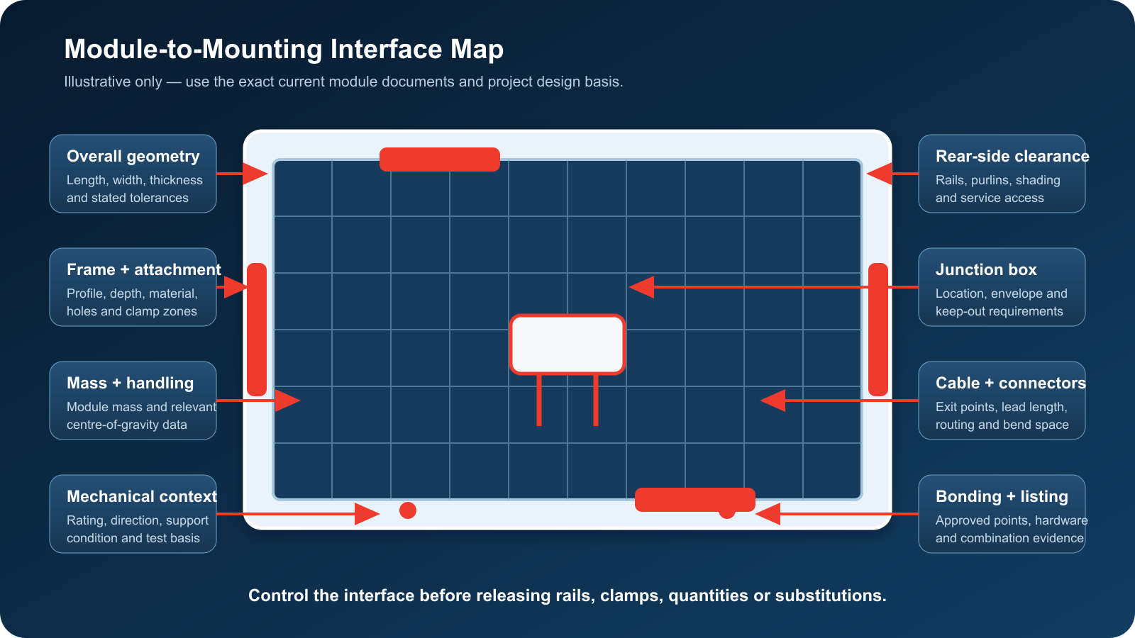
A proposed module or layout change must be compared against the installed configuration field by field. Start with the module-to-mounting inputs and extend the review through the retained asset.
| Interface | Compare old, installed and proposed states | Evidence needed for disposition |
|---|---|---|
| Module attachment | Frame geometry, approved clamp zones or mounting holes, orientation, edge distance, clamp or bolt type, bearing surface and installation torque basis | Current module instructions, rack instructions, applicable evaluated combination, detailed interface drawing and approved work method |
| Structural load path | Module area and mass, table geometry, spans, cantilevers, wind and snow actions, load direction, bracing, rail/purlin/member demand and retained capacity | Project design basis, site-specific actions, verified field geometry, condition allowances and accountable engineering calculation |
| Foundation or building support | Reaction changes, existing support capacity, movement or deterioration, roof structure, attachments, ballast, waterproofing and drainage | Geotechnical/structural or roof assessment, as-built support identity, inspection results and project approval |
| Bonding and earthing | Listed or designed bonding path, contact surfaces, coatings, hardware, conductor route, continuity and any removed or replaced element | Applicable electrical design, product evidence, installation instructions, inspection and test plan |
| Rooftop fire route | Module and rack combination, roof assembly, clearances and installation conditions where the project uses a listing-based fire classification | Exact listing parameters, named combination and authority review for the jurisdiction |
| Electrical and access envelope | Connector and cable reach, string design, wire management, edge protection, equipment clearance, walkways, drainage and maintenance access | Electrical redesign where affected, coordinated layout and constructability review |
IEC 62548-1:2023 covers PV-array design requirements and notes revised mounting-structure provisions in its current edition. It does not provide a universal reuse approval. Apply the edition, national adoption and project scope selected by the responsible design team.
For projects using a US certification route, the official UL Solutions Question Corner on UL 2703 explains that mounting, clamping and grounding products may be certified for specific functions, modules, components and installation criteria. It also identifies mechanical loading, grounding and bonding, and fire classification as distinct attributes that may apply to a represented combination. “UL 2703 compliant” on a data sheet is not a substitute for verifying the exact certification parameters and intended use.
Keep jurisdiction-specific routes separate. A UL listing, an IEC design requirement, a project calculation and an authority approval answer different questions. None should be presented as a universal certificate of structural reuse.
Decide by Zone: Retain, Repair, Adapt or Replace
Use a disposition ledger rather than a single reuse percentage. Each row should name the zone, existing identity, proposed duty, evidence reviewed, unresolved delta, decision, work scope, inspection route and approval authority.
| Disposition | Minimum basis | Permitted work | Stop trigger |
|---|---|---|---|
| Retain as installed | Identity and geometry reconciled; condition acceptable; proposed duty does not invalidate design, interface evidence or approval | Protect the rack during module work; replace only approved consumables or components under the work plan | Any field difference outside the verified population or any damage caused during removal |
| Repair and retain | Repairable defect has a designed or approved restoration method and acceptance criteria | Execute the named repair, inspect the repaired area and update the condition record | Crack, deformation, section loss, movement or connection damage outside the repair basis |
| Adapt and requalify | Change is defined; retained load path and interfaces are verified; adapter or strengthening is engineered and traceable | Install the controlled modification in identified zones and prove representative execution | Unverified parent material, inaccessible critical joint, incompatible listing route or failed representative check |
| Replace | Reuse cannot be demonstrated, condition is unacceptable, required evidence is unavailable, or conversion risk outweighs the retained value | Remove under a safe sequence and install the approved replacement system | Retained foundations, roof attachments or adjacent racks cannot meet the new interface basis |
| Hold | Evidence conflict, access limitation, open authority question or failed test prevents a defensible disposition | Isolate the affected population and obtain the missing decision input | No work beyond agreed stabilization and investigation |
The decision may be mixed. A sound foundation does not automatically justify retaining every member above it. A serviceable rail does not prove that a new module, clamp and bonding arrangement is acceptable. Conversely, replacement of modules and inverters does not automatically require removing verified foundations or racking. The Natural Bridges rehabilitation example illustrates that selective retention can be a valid project outcome after assessment; it does not define the assessment for other sites.
Record the remaining service requirement as a project input, not an assumed property. The engineer and owner must define post-repower duty, design basis, inspection scope, deterioration allowances, maintenance strategy and acceptance criteria. Avoid converting age or visual appearance into a capacity or life claim.
Prove the Conversion Before Full Rollout
Choose a representative conversion zone that includes the most consequential retained interfaces. A convenient central table may miss perimeter wind exposure, roof-edge conditions, unusual foundations, repair history or the worst access constraint. More than one trial zone may be necessary when the plant contains materially different families.
The proof plan should distinguish four questions:
- Engineering applicability: Does the calculation or evaluation represent the verified geometry, condition, module, connection, support and post-work duty?
- Installation executability: Can the crew remove modules and install retained, repaired or adapted components without uncontrolled damage, instability or ambiguity?
- Inspection detectability: Are the critical characteristics accessible, measurable and tied to acceptance criteria?
- Configuration repeatability: Can the approved method be reproduced across the identified population with controlled parts, instructions and records?
The DOE’s current guidance on installing and commissioning photovoltaic systems treats racking, critical fastened joints, system-type conditions and commissioning as connected considerations. Use the applicable project requirements to define fastener replacement, tightening, testing and inspection. Do not copy a generic torque value, sample rate or repair method into a repowering plan.
Run the representative work under the real revision-controlled instructions. Reconcile removed parts, replacement components and adapters. Record unexpected hole positions, distorted members, coating damage, inaccessible joints, cable conflicts and any field decision needed to complete the work. If the trial succeeds only through undocumented adjustment, the rollout method is not ready.
Update the engineering basis and work instruction after resolving trial findings. Then release only the represented zones. Keep unverified families held until their differences are assessed.
Establish a New Post-Repower Configuration Baseline
Repowering ends with a new controlled asset record, not with the last module installed. The handover pack should let an operator identify what changed, what remained, why each retained item was accepted, and which conditions govern future work.
Include the pre-work survey and exception map, old-to-new interface delta register, approved calculations and drawings, listing or evaluation applicability records where used, repair and adaptation details, component identities, installation and inspection records, test results, nonconformance closure, as-built zone plan, photographs, operating limits, maintenance actions and spare-part rules. Link each record to the zone and configuration it represents.
IEC 62446-1:2016+A1:2018 defines documentation, commissioning tests and inspection information for grid-connected PV systems. Apply the current project-selected edition and local requirements. Its documentation boundary reinforces a practical point: the new system state must be verifiable after the conversion team leaves.
Carry the closed baseline into the project’s installation handover controls and O&M system. Future repairs should reference the post-repower configuration, not an obsolete original BOM or a contractor’s temporary redline.
Related Resources
- Solar Mounting Systems for new-system scope and project inquiry inputs.
- Module Datasheet Inputs for Solar Mounting Design for the geometry, attachment and electrical fields that can reopen a mounting review.
- Solar Mounting Wind Load for building a site-specific wind-evidence chain.
- Solar Mounting Installation Handover for zone-level as-built and closeout records.
References
- US Department of Energy — Off-Grid Photovoltaics Rehabilitation at Natural Bridges National Monument
- NREL — Best Practices for Operation and Maintenance of Photovoltaic and Energy Storage Systems
- IEC 62548-1:2023 — Photovoltaic Arrays, Part 1: Design Requirements
- UL Solutions — UL 2703 Question Corner
- US Department of Energy — Install and Commission a Photovoltaic System
- IEC 62446-1:2016+A1:2018 — Documentation, Commissioning Tests and Inspection
Next Step: Issue One Zone Repowering Decision Pack
Send one identifiable zone rather than a plant-wide reuse request. Include the existing and proposed module data, array and support geometry, available approved drawings and calculations, site photographs tied to locations, condition findings, repair history, environmental and load basis, electrical and bonding requirements, applicable listing or approval route, intended post-repower duty, and the proposed work sequence. East Baoyu can review input completeness, manufacturability, interface definition and the evidence package for an agreed supply scope. The project’s appointed structural, electrical, roofing, geotechnical and fire/code authorities retain responsibility for design methods, site acceptance and final approval. Use the resulting pack to decide retain, repair, adapt, replace or hold for each zone before procurement and rollout.
References, disclosure and change record
References and further verification
- https://eastbaoyu.com/solar-mounting/
- https://www.energy.gov/cmei/femp/grid-photovoltaics-rehabilitation-national-park-services-natural-bridges-national
- https://www.osti.gov/biblio/1489002
- https://eastbaoyu.com/module-datasheet-inputs-needed-solar-mounting-design/
- https://webstore.iec.ch/en/publication/64171
- https://code-authorities.ul.com/wp-content/uploads/sites/46/2022/09/Sept-Oct-2022-UL-Question-Corner_FINAL.pdf
- https://www.energy.gov/cmei/femp/life-cycle-photovoltaic-systems-install-and-commission-photovoltaic-system
- https://webstore.iec.ch/en/publication/63726
- https://eastbaoyu.com/solar-mounting-installation-handover/
- https://eastbaoyu.com/solar-mounting-wind-load/
Disclosure: East Baoyu manufactures and supplies products discussed on this website. Structured drafting tools may assist research and editing, but technical claims, project inputs and release decisions require qualified review under the applicable project responsibilities.
Version 1.0: Scheduled as EB50-035 on 2026-09-06.
View the public Content Change Log · Corrections: info@baolaipipes.com