

Authorship, review and evidence boundary
- Technical review
- East Baoyu Engineering Editorial Team
- Reviewed
- 2026-09-06
- Scope
- General engineering and procurement guidance. This article is not a project-specific design, capacity statement, certificate, warranty, code interpretation or contract requirement.
Evidence basis: Official and public references identified in the article. Project values and release decisions require qualified review under the applicable project responsibilities.
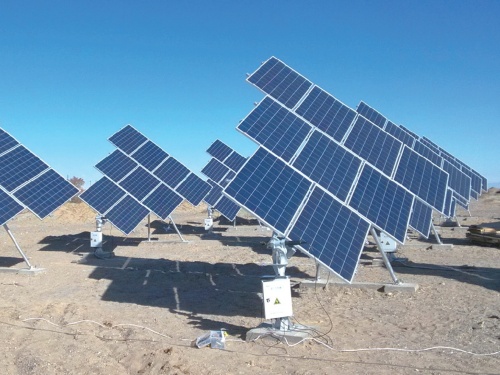
Read the Editorial PolicyA solar tracker can pass individual controller checks and still fail the project’s protective intent. A weather input may reach the supervisory system while one row follows the wrong command, reports the wrong identity, stops short of its required position or disappears from the event record. Solar tracker stow validation therefore has to prove one connected result: the approved initiating condition reaches the correct installed population, each required row responds within the project criteria, the response is confirmed, and abnormal branches remain visible. This guide starts after the stow strategy has been approved. It does not set wind thresholds, stow angles or structural limits; it shows how commissioning and change-control teams can demonstrate that the installed response chain matches that approved basis.
Freeze the Claim Before Starting a Test
“The tracker stows” is too vague to test. Define the exact claim, population, configuration and decision that the evidence must support. A commissioning test may be intended to release one control zone, accept the whole plant, confirm a repaired block or validate a software change. Those decisions need different evidence boundaries.
Start with a Stow Validation Basis. Identify the approved design or stow-basis revision, protective mode, controller and firmware baseline, parameter-set identity, weather-input source, communications topology, power arrangement, row population and physical position definition. Also freeze the initiating condition, start and finish event markers, abnormal branches, acceptance authority, test restrictions and exclusions. This prevents a successful demonstration of one convenient path from being presented as proof of the complete protective function.
The broad solar tracker wind-load and stow-strategy guide owns the design question: which states, triggers and structural assumptions the project should use. Validation begins only when those requirements are controlled. If the basis is still disputed, stop the test plan and return the question to the responsible structural, tracker and controls authorities.
Map One End-to-End Evidence Chain
A command at a laptop is not proof of row position. Likewise, a row seen at an angle is not proof that the correct initiating logic, identity, timing and alarm path worked. Build an evidence map that joins every transition from input to confirmed outcome.
For each transition, name the source record, identifier and time reference. The input needs an identity; the supervisory event needs a logic version; the command needs a destination; the controller needs a mapped asset; and motion evidence and returned status must reconcile to the same physical row.
The IEC publication record for IEC 62817 describes design qualification applicable to solar trackers and test procedures for key components and the complete system. That scope supports system-level thinking, but type or design qualification is not a substitute for proving the configuration installed at a particular plant. Commissioning evidence must connect the project’s approved logic to its actual sensors, network, controllers, drives, rows and records.
Use two observation routes for the decisive physical outcome when project risk justifies it. One may be controller feedback; the other can be an approved field measurement or witnessed position check. A disagreement is a result to investigate, not a reason to select the convenient value.
Turn Requirements into Observable Pass or Hold Criteria
Translate each approved requirement into events that can be observed and reconciled. Avoid a test script that says only “activate wind stow; verify operation.” It leaves the start point, finish point, required population and treatment of missing data undefined.
Define the response interval with explicit markers. The start might be the qualifying input state recognized by the approved logic, not the moment an operator clicks a manual command. The finish might require confirmed physical position for every addressed row, not the first controller acknowledgement. Which markers are correct depends on the project basis; the validation plan must not invent a universal definition.
Separate four statuses:
- Commanded: the supervisory layer issued an instruction to a named destination.
- Acknowledged: the receiving controller reported receipt or state transition.
- Physically achieved: the identified row reached the project-defined position using an accepted measurement route.
- Protective function confirmed: all required population, timing, alarm, abnormal-state and recovery criteria are closed.
Do the same for alarms. State which condition should create the alarm, where it must appear, whether it latches, what identity and timestamp it carries, who receives it and what operational response follows. “Alarm generated” is not a complete criterion if the control room cannot distinguish the affected zone or the event is absent from the retained history.
Never copy an example threshold, angle, delay, travel time, sampling interval or recovery rule from another site. The 2024 IEA PVPS report on bifacial photovoltaic tracking systems explains that extreme-weather response, stow thresholds and angles vary between tracker designs and suppliers, and it highlights the risk of inappropriate response. The project’s current structural and control basis must supply the numbers.
Cover Normal, Protective and Degraded Branches Safely
Build a Scenario Coverage Matrix from the approved cause-and-effect logic. The matrix should prove paths, not create hazardous field experiments. Live environmental conditions are not a controllable test source, and no commissioning team should wait for or manufacture a dangerous wind event.
| Scenario family | What the scenario is meant to prove | Typical observations | Boundary before execution |
|---|---|---|---|
| Normal protective entry | Correct input evaluation, addressed population, motion, confirmation and alarm/status behavior | Input event, decision event, outbound command, row response, physical position and operator display | Use only the project-approved injection or simulation point and safe operating state |
| Partial communications loss | Approved behavior when a controller group or row cannot receive or report | Loss detection, command path, affected identity, local behavior, alarm and operating restriction | Do not assume that a communications test proves power-loss behavior |
| Sensor unavailable or implausible | Approved fallback when the primary input is lost, stale, inconsistent or outside a valid route | Input-quality flag, fallback selection, protective state and operator notification | Follow approved controls; validation does not design the fallback |
| Power interruption or backup transition | Intended response of supervisory, communications and row-control layers during the defined power case | Power-state events, retained logic, row response, alarms and recovery evidence | Coordinate electrical safety, stored-energy and mechanical hazards before testing |
| Motion or position discrepancy | Detection and containment of a row that cannot achieve or confirm the required state | Command, drive current/status where available, physical observation, alarm and exception record | Do not continue repeated motion against an unknown obstruction or damaged mechanism |
| Recovery from protective state | Authorized exit, reset, return sequence and restoration of monitoring | Release condition, permission, staged movement, alarms cleared and stable normal status | Recovery is a separate approved action, not an automatic reward for passing entry |
The method for generating a test condition must be documented. Identify whether the input is injected at a sensor interface, a control application, a network point or another approved layer, and state which upstream functions that method bypasses. A software injection after the weather-processing layer, for example, cannot prove sensor location, calibration, input quality or upstream communications. Mark bypassed elements as untested and close them through another scenario or record.
Before any powered motion, confirm work-area control, exclusion zones, mechanical condition, module and cable clearance, authorized personnel, communications, emergency stop arrangements and the project’s safe test state. If an unexpected sound, obstruction, current signature, structural movement or position mismatch appears, pause and route the condition through the responsible site process. This article cannot authorize energization or define a safe operating envelope.
Select Coverage by Architecture, Not a Flat Percentage
A simple sample percentage can miss the one architecture branch most likely to fail. Divide the installed population by characteristics that change the evidence chain: weather-input source, supervisory node, network segment, controller or firmware family, parameter set, drive arrangement, backup-power source, terrain or row geometry where relevant, and installation or repair history.
Then decide what needs full-population evidence and what can be witnessed on representative units. Digital logs may allow the team to screen every row for command receipt, timing, completion status and exceptions. Physical position checks may use a risk-based sample if the project authority accepts it. The plan should deliberately include boundaries, longest communication paths, different controller groups, recently changed rows and units with earlier defects—not only convenient rows beside the control room.
Create a Population Coverage Register with one line per row or controlled asset. Minimum fields include physical row ID, controller address, zone, configuration revision, scenario coverage, evidence filenames or log keys, physical-check status, exception status and release disposition. Reconcile counts: rows in the controlled asset register should equal rows included, formally excluded with reason, or held. An unexplained difference is a release blocker.
The solar tracker installation guide covers row qualification and plant-level commissioning in the wider construction sequence. The validation described here is narrower: it proves the stow-specific signal-to-safe-state chain for a defined baseline and leaves a record that can be repeated after change.
Preserve Chronology, Identity and Raw Evidence
End-to-end timing is only defensible when clocks and identities can be reconciled. Record the clock source, synchronization status and offset checks for weather devices, supervisory servers, gateways, row controllers, operator displays and external measurement systems used in the decision. Do not silently subtract timestamps from unsynchronized devices.
Before execution, capture the configuration baseline and export method. During execution, retain raw or native event data where possible before filtering it into a summary. After execution, protect both the source files and the interpretation. Screenshots can help a witness understand a moment, but they usually omit preceding events, tag definitions, sampling behavior and later corrections.
Use an End-to-End Evidence Map:
| Evidence object | Required join keys | Quality check | Release use |
|---|---|---|---|
| Input record | source ID, tag, engineering units, quality flag, timestamp | Correct source and approved processing route; no unexplained gaps | Proves the scenario entered the intended logic path |
| Logic and command record | application/version, rule or state, destination group, timestamp | Baseline matches the frozen configuration | Proves the approved logic issued the intended command |
| Controller/drive record | controller and row ID, command, state, position/feedback, fault, timestamp | Asset mapping and status definitions verified | Proves receipt, motion state and controller-reported outcome |
| Physical observation | physical row ID, method, instrument/check status, observer, timestamp | Measurement route and identity are controlled | Corroborates the actual installed position or discrepancy |
| Operator/alarm record | alarm tag, affected asset/zone, priority or route, acknowledgement, history | Visible at required destination and retained | Proves operational awareness and response route |
| Signed test result | scenario ID, population, pass/hold, exceptions, witnesses, attachments | Every conclusion traces to raw evidence | Supports bounded release and future regression comparison |
Retain failed attempts and invalid tests with their reason. Removing them creates a misleading history and can conceal intermittent behavior. If a test is invalid because a clock was wrong or an injector bypassed the wrong layer, label it invalid, correct the method and rerun under control.
Classify Discrepancies Before Choosing Regression Scope
Not every failed observation has the same cause or consequence. Classify the discrepancy at the transition where evidence first breaks, contain the affected population, and then decide what must be corrected and retested.
| First evidence break | Examples of the question to investigate | Immediate disposition | Regression focus after correction |
|---|---|---|---|
| Input or quality state | Wrong sensor/tag, stale value, unit or scaling issue, missing quality flag | Hold claims that depend on that input path | Reprove input processing plus every downstream scenario it can affect |
| Logic or baseline | Wrong firmware, parameter set, state rule, zone table or unauthorized change | Freeze configuration and affected release | Reconfirm baseline, repeat affected cause-effect branches and check adjacent logic |
| Addressing or communications | Wrong row mapping, missed destination, delayed path, intermittent network segment | Identify and contain the mapped population | Repeat population reconciliation, command delivery, timing and exception visibility |
| Motion or mechanism | Obstruction, direction error, drive/connection problem, incomplete travel | Stop unsafe repetition and inspect the exact row/system | Requalify repaired hardware, motion path, physical outcome and protective scenario |
| Feedback or alarm | Physical state differs from reported value, missing alarm, wrong identity or lost history | Treat status as untrusted for the affected route | Reprove sensing/feedback, operator visibility and dependent automated decisions |
| Test method or evidence | Injection bypass, unsynchronized clocks, missing raw log, witness gap | Mark test invalid; do not convert it to a conditional pass | Correct the method and repeat enough of the chain to support the original claim |
A corrective action is not automatically a narrow retest. Firmware, shared parameters, network maps or supervisory logic can affect more than the row where a discrepancy appeared. Conversely, a verified local repair may not require repeating an unrelated sensor path. Define regression scope from the changed item, its dependencies and the earlier evidence it could invalidate.
For an unexpected in-service event or active fault, use the separate solar tracking system fault-triage guide to isolate before restart. Validation is a planned release activity; triage is a reactive containment and diagnosis route.
Release a Baseline That Can Be Revalidated
Issue one Stow Validation Release Record rather than scattering acceptance across meeting notes and screenshots. The record should state the claim, approved basis, tested configuration, included population, scenario results, raw-evidence index, exceptions, corrective actions, residual limitations, operating restrictions, approvals and the exact baseline released.
Use three dispositions: released, released with explicit controlled limitations where the contract and accountable authorities permit it, or held. Do not use “substantially complete” to cover an unknown population, unexplained timing gap or unverified fail-state branch. A concession is a controlled decision with owner, scope and expiry or closure condition; it does not rewrite the design basis silently.
Define revalidation triggers in the handover package. Examples include changes to firmware, supervisory applications, parameter files, sensor type/location/calibration route, communications architecture, row addressing, power or backup arrangements, actuator/drive family, position feedback, cause-effect logic or the approved structural stow basis. Also consider revalidation after repairs or observed events that call the released chain into question.
ISO 10007:2017 provides configuration-management guidance across the product lifecycle. Applied here, the useful discipline is to identify the released configuration, control changes, account for status and verify the resulting configuration. The project contract and its accountable authorities determine the exact records and approvals.
At handover, the operator needs more than a passing certificate. Provide the controlled baseline, row/address map, cause-effect matrix, input and alarm tag definitions, scenario scripts, raw-data locations, exception history, recovery authority, known limitations and revalidation triggers. That package turns commissioning into a repeatable comparison point instead of a one-time demonstration.
Related Resources
- Solar Tracker Wind Load and Stow Strategy — define the structural and control basis before validation.
- Solar Tracker Installation — coordinate row qualification and whole-plant commissioning.
- Solar Tracker Slew Drive — review the drive, structure and control interface when motion evidence breaks.
- Solar Tracking System Fault Triage — contain and isolate an active fault before return to service.
- Solar Tracking Bracket — East Baoyu’s product and project-routing page for tracker structures.
References
- IEC 62817:2014+AMD1:2017 consolidated version — official publication record
- IEA PVPS T13-26:2024 — Best Practices for the Optimization of Bifacial Photovoltaic Tracking Systems
- ASCE MOP 162 — Design and Construction of Solar Photovoltaic Systems
- ISO 10007:2017 — Quality management: Guidelines for configuration management
Next Step
If your approved tracker design is entering commissioning or a released control baseline has changed, send East Baoyu the controlled tracker configuration, zone and row map, interface drawings, approved stow basis, scenario requirements and evidence-delivery list. Email info@baolaipipes.com. We can review the supplier-side structural configuration, row interfaces, manufacturing records and inspection evidence that must reconcile with your validation package. Project designers, tracker/control providers, commissioning authorities and the owner retain responsibility for logic, numerical criteria, safe test methods and final release.
References, disclosure and change record
References and further verification
- https://eastbaoyu.com/solar-tracker-wind-load-and-stow-strategy/
- https://webstore.iec.ch/en/publication/61127
- https://iea-pvps.org/wp-content/uploads/2024/08/IEA-PVPS-T13-26-2024-REPORT-Bifacial-Tracking_FINAL.pdf
- https://eastbaoyu.com/solar-tracker-installation/
- https://eastbaoyu.com/solar-tracking-system-fault-triage/
- https://www.iso.org/standard/70400.html
- https://eastbaoyu.com/solar-tracker-slew-drive/
- https://eastbaoyu.com/solar-mounting/solar-tracking-bracket/
- https://ascelibrary.org/doi/10.1061/9780784486849
Disclosure: East Baoyu manufactures and supplies products discussed on this website. Structured drafting tools may assist research and editing, but technical claims, project inputs and release decisions require qualified review under the applicable project responsibilities.
Version 1.0: Scheduled as EB50-042 on 2026-09-06.
View the public Content Change Log · Corrections: info@baolaipipes.com