

Authorship, review and evidence boundary
- Technical review
- East Baoyu Engineering Editorial Team
- Reviewed
- 2026-09-05
- Scope
- General engineering and procurement guidance. This article is not a project-specific design, capacity statement, certificate, warranty, code interpretation or contract requirement.
Evidence basis: Official and public references identified in the article. Project values and release decisions require qualified review under the applicable project responsibilities.
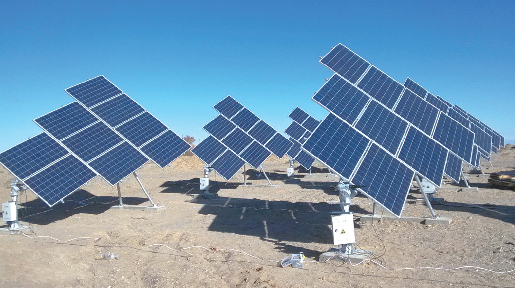
Read the Editorial PolicyA fixed-tilt solar project can sometimes switch to trackers, but the change is feasible only after the project reopens every affected assumption and approval. It is a mounting-architecture change, not a racking substitution. The original energy layout, land envelope, survey, civil works, loads, foundations, electrical routes, control strategy, permits, work packages and commercial model may no longer describe the proposed plant. The later the proposal arrives, the more work may be stranded. Preserve the fixed-tilt baseline, build a separate tracker branch and classify prior evidence as carry over, revalidate or rebuild. Do not release procurement or construction until one authorized change charter defines the new basis and its gates.
Treat the Proposal as an Architecture Change
Start with a precise question: Can this project change architecture at its present stage, under its actual site, approval, schedule and contract constraints? That differs from asking whether trackers are generally better than fixed tilt. The broad comparison belongs in a transparent energy and commercial model. The late-change decision must also account for work already performed and commitments already made.
A software change can make the switch appear deceptively small. The U.S. National Renewable Energy Laboratory's System Advisor Model PV design guidance treats fixed and one-axis tracking as different tracking modes. The one-axis route introduces settings such as rotation limits, backtracking, ground coverage ratio and terrain-related behavior. SAM also warns that changing the tracking option does not automatically change installation or operating costs. This is an important boundary: changing a model setting does not convert the underlying project.
Freeze the last accepted fixed-tilt state before exploring the tracker option. Record its layout and energy-model version, site boundary, module configuration, design zones, survey surface, geotechnical basis, foundation route, structural issue, electrical architecture, approvals, RFQ status, orders and field work. This becomes the counterfactual baseline. Without it, teams may combine a new tracker yield with old fixed-tilt quantities and an incomplete estimate of redesign.
Name the tracker proposal separately. Give it a branch identifier, owner, comparison cut-off date and permitted scope. The tracker branch should not silently overwrite fixed-tilt files while the decision remains open.
Locate the Project on the Irreversibility Clock
The same tracker idea has a different consequence at concept stage and after foundations have been ordered. Use an irreversibility clock to set the review depth before calculating potential benefit.
| Project state | Fixed-tilt work that may exist | Tracker-change consequence | Minimum management response |
|---|---|---|---|
| Screening | Preliminary site and energy assumptions | Most inputs remain flexible; comparison uncertainty is high | Run two clearly bounded concepts with common source data |
| Modelled option | Layout, yield model, indicative civil and structural assumptions | Several deliverables must be regenerated, but little physical work is committed | Freeze both model versions and reconcile comparison boundaries |
| Approved basis | Accepted design basis, permit submissions, land plan or internal investment approval | The change can reopen technical and external approvals | Map every approval and identify the authority that can reopen it |
| Committed procurement | RFQs, purchase orders, reserved capacity, fabricated items or logistics commitments | Cancellation, substitution and schedule exposure may dominate | Quantify committed and recoverable scope before authorizing redesign |
| Site execution | Grading, roads, cables, foundations or installed equipment | Rework, safety, environmental and interface consequences become location-specific | Place affected work on hold and obtain project-specific engineering and commercial decisions |
This clock is not a formula and does not impose a universal point of no return. A project can have mixed states: civil work may be active while the mounting package remains unawarded. Record maturity by workstream and physical area. The decision boundary should follow the most consequential dependency, not the average percentage complete.
Distinguish sunk work from avoidable future commitment. Already spent effort matters for record integrity and rework, but it should not alone decide the architecture. The practical question is which future costs, delays and risks each option creates from the decision date, including disposition of work already committed.
Map the Full Change Radius
Trackers change more than the moving steel. Their geometry, actions, controls and operating states can reach across the plant. Build a change-radius map before asking disciplines for a quick approval.
| Domain | Fixed-tilt baseline to expose | Tracker question to reopen | Evidence needed before acceptance |
|---|---|---|---|
| Energy and layout | Tilt, azimuth, pitch, shading, losses and exclusions | Rotation range, backtracking, ground coverage, terrain treatment and operational losses | Controlled parallel model, common weather basis and difference register |
| Land and permits | Boundary, setbacks, height envelope, visual or environmental commitments | Changed row envelope, motion, access or height implications | Constraint map and approval-authority response |
| Survey and civil | Datum, surface, grading, drainage, roads and tolerances | Tracker slope capability, row alignment, water paths and access requirements | Reissued grading/access concept tied to tracker zones |
| Structural and wind | Fixed-table geometry, load path and design actions | Multiple tracker positions, dynamic behavior, drive/torque path and stow assumptions | Tracker-specific design basis and qualified structural assessment |
| Ground and foundations | Investigation coverage, reactions, support layout and test basis | Different post locations, reaction components, movement limits and installation population | Updated ground-to-foundation map and project-specific verification plan |
| Electrical | String arrangement, cable lengths, routes, clearances and earthing | Moving interfaces, loops, row equipment, route changes and maintenance states | Revised single-line/interface documents and cable management review |
| Controls and communications | Fixed-array monitoring assumptions | Controllers, communications, sensors, power, alarms, safe states and recovery | Control architecture, cause/effect basis and acceptance tests |
| Construction and logistics | Work sequence, temporary stability, packages, lifting and access | Drive installation, alignment, commissioning, workface and spares implications | Revised construction strategy and interface register |
| Operations and maintenance | Cleaning, vegetation, inspection and access plan | Moving equipment, stow/recovery, fault isolation and replacement strategy | O&M concept, competence needs and spare-parts basis |
| Commercial and documents | Scope split, price basis, warranties, approvals and schedule | New responsibilities, exclusions, evidence, cancellations and re-release dates | Controlled change estimate and revised responsibility/document register |
The map defines questions; it does not answer them. The responsible designers and approval authorities determine whether the proposal complies with the project's governing requirements. A supplier can clarify system interfaces and provide controlled product information, but it cannot inherit unnamed project-design responsibilities through a sales comparison.
Do not mark a domain “unchanged” merely because the same module or site remains. Evidence carries forward only when its purpose, inputs, population, configuration and acceptance basis remain applicable.
Sort Existing Work into Carry Over, Revalidate or Rebuild
Give every material deliverable one disposition. “Review” is too vague because it hides whether the record remains usable.
| Disposition | Meaning | Example | Closure evidence |
|---|---|---|---|
| Carry over | The controlled record and its applicability remain unchanged | Legal site boundary or a verified survey control point, if the tracker branch uses the same basis | Named record, revision and reason applicability survives |
| Revalidate | Source evidence may remain useful, but conclusions or coverage must be tested against tracker inputs | Geotechnical investigation, environmental constraint map or module data | Responsible reviewer confirms limits, gaps and required supplements |
| Rebuild | The output represents fixed-tilt architecture and cannot define the tracker branch | Row layout, tracker structural model, control logic or moving-cable design | New tracker-specific deliverable and approval |
| Retire or supersede | The record must not be used for the selected branch | Obsolete fixed-tilt BOM or setting-out file after tracker approval | Superseded status, distribution control and archive link |
Apply the classification to models, calculations, drawings, specifications, quantities, RFQs, purchase orders, permits and site instructions. Keep a reason and accountable owner for each disposition. A prior survey may carry over as measured data while the civil conclusions drawn from it require revalidation. A geotechnical report may remain a source record while its exploration coverage is insufficient for the revised support population. A fixed-tilt foundation calculation should not be renamed as a tracker foundation calculation.
Link the register to locations and packages. If only one project zone is considering trackers, do not reopen unaffected fixed-tilt blocks without cause. Conversely, do not declare a local tracker pilot when its electrical, control, access or approval dependencies cross the zone boundary.
Build a Clean Tracker Branch
The tracker option needs a coherent baseline before it can compete with the fixed-tilt baseline. At minimum, define the module arrangement, row length and segmentation, rotation convention and limits, ground coverage, terrain rules, support and drive architecture, control and communications boundary, operating states, maintenance access and environmental design inputs. Undefined fields should remain visible as assumptions or holds.
The current consolidated IEC 62548-1:2023 with Amendment 1:2025 covers PV-array design requirements and includes mounting-structure provisions. The current consolidated IEC 62817:2014 with Amendment 1:2017 addresses design qualification for solar trackers, including key components and complete tracker systems. These standards help identify relevant technical boundaries; they do not approve a particular architecture switch or replace local structural, electrical, geotechnical, permitting and contractual requirements.
Operating behavior must also appear in the comparison. The IEA PVPS Task 13 report on best practices for the optimization of bifacial photovoltaic tracking systems discusses matters such as tracking algorithms, backtracking, stow strategies, commissioning and the relationship between design information and field implementation. Use that context to request project evidence, not to copy a generic stow value or performance claim.
Compare the branches on a common cut-off date and boundary. State which energy inputs, land area, grid limits, degradation assumptions, losses, cost categories, schedule dates and residual risks are common and which differ. Include redesign, cancelled or repurposed commitments, controls, commissioning, spares and operating obligations where applicable. If an input cannot yet be estimated responsibly, record a range, hold or decision sensitivity rather than silently setting it to zero.
Test Whether a Reversible Path Still Exists
A reversible path lets the team learn enough about the tracker option without corrupting the fixed-tilt baseline or creating uncontrolled commitments. Test the path with six questions:
- Can affected fixed-tilt packages pause at a named boundary without creating a larger safety, permit, schedule or commercial problem?
- Can the tracker branch reach a comparable evidence state before the next irreversible commitment?
- Are the site, terrain, ground, wind, electrical and approval inputs available at sufficient coverage for that branch?
- Can committed fixed-tilt material or services be cancelled, reassigned or completed without assuming an unverified recovery value?
- Are new tracker responsibilities, operating states and acceptance tests assigned to competent parties?
- Does the decision remain favorable when unresolved items are treated as risks or holds rather than free benefits?
Proceed with the switch only when the new baseline can re-enter the project's release process and the accountable authority accepts the full consequence. Maintain a bounded parallel option when decisive evidence can be obtained before commitment. Defer when the option may become viable at a later phase or area without disrupting the current release. Reject the switch when an immovable constraint, unacceptable exposure or unavailable approval path governs.
Avoid a false choice between “approve trackers now” and “never use trackers.” A split architecture, future phase, pilot area or later portfolio project may be a legitimate outcome, but each creates its own interfaces and must be assessed rather than assumed.
Release the Change Through One Charter
The Mounting-Architecture Change Charter is the authorization boundary for the option study and, if accepted, the re-entry into design release. Keep it concise enough to govern work but specific enough to prevent parallel teams from using different assumptions.
The charter should contain:
- the decision owner, technical authorities and commercial authority;
- the fixed-tilt baseline identifier and exact frozen date;
- the tracker branch identifier, physical scope and exclusions;
- the decision deadline and next irreversible commitments;
- common comparison inputs and explicitly different inputs;
- the change-radius map with owner and response date for every domain;
- the carry-over, revalidate, rebuild and supersede register;
- holds on procurement, fabrication, construction and document release;
- tracker evidence, calculation, test and approval deliverables;
- treatment of existing orders, work in progress and site work;
- decision criteria, unresolved-risk treatment and approval record; and
- branch closure: selected baseline, superseded files and distribution notice.
Do not let the charter itself become a technical approval. It organizes responsibilities, inputs and gates. Each specialist remains accountable within the project contract and governing requirements. When the tracker branch wins, issue a new controlled baseline and re-run the affected release gates. When fixed tilt remains selected, close the tracker branch and preserve the decision record so the same unsupported proposal does not repeatedly reopen the project.
A late switch from fixed tilt to trackers can be rational, but feasibility depends on the whole project state. Preserve the old baseline, expose the change radius, reclassify prior evidence and compare two coherent branches. The best outcome is not the architecture with the most attractive isolated number; it is the architecture that can be designed, approved, procured, built and operated on a controlled evidence basis.
Related Resources
- Fixed versus Tracking PV: How to Build a Defensible Energy Comparison owns the broad alternative comparison and energy/economic boundary.
- Single-Axis Solar Tracker: Freeze the Row Architecture defines the tracker row and evidence architecture.
- Fixed-Tilt Solar Mounting Design: Reconcile Every Model shows how to preserve a coherent fixed-tilt baseline.
- Solar Mounting Systems is the parent route for project mounting discussions.
References
- NREL System Advisor Model — PV system design
- IEC 62548-1:2023+AMD1:2025 — Photovoltaic arrays, Part 1: Design requirements
- IEC 62817:2014+AMD1:2017 — Photovoltaic systems, Design qualification of solar trackers
- IEA PVPS Task 13 — Best Practices for the Optimization of Bifacial Photovoltaic Tracking Systems
Next Step: Issue the Architecture Change Charter
Freeze the accepted fixed-tilt baseline and complete the irreversibility clock, change-radius map and evidence-disposition register before requesting a tracker quotation. Send the bounded package to export@eastbaoyu.com and use the Solar Tracking Bracket route to discuss row configuration and supply interfaces. East Baoyu can identify missing system inputs and product-scope boundaries; project energy, civil, structural, geotechnical, electrical, permitting and release decisions remain with the authorized project parties.
References, disclosure and change record
References and further verification
- https://webstore.iec.ch/en/publication/64171
- https://webstore.iec.ch/en/publication/61127
- https://www.iea-pvps.org/wp-content/uploads/2024/08/IEA-PVPS-T13-26-2024-REPORT-Bifacial-Tracking_FINAL.pdf
- https://eastbaoyu.com/fixed-versus-tracking-pv-energy-comparison/
- https://eastbaoyu.com/single-axis-solar-tracker/
- https://eastbaoyu.com/fixed-tilt-solar-mounting-design/
- https://eastbaoyu.com/solar-mounting/
- https://eastbaoyu.com/solar-tracking-bracket/
Disclosure: East Baoyu manufactures and supplies products discussed on this website. Structured drafting tools may assist research and editing, but technical claims, project inputs and release decisions require qualified review under the applicable project responsibilities.
Version 1.0: Scheduled as EB50-026 on 2026-09-05.
View the public Content Change Log · Corrections: info@baolaipipes.com