

Stadium & Sports Center
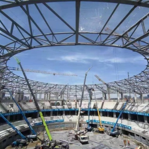
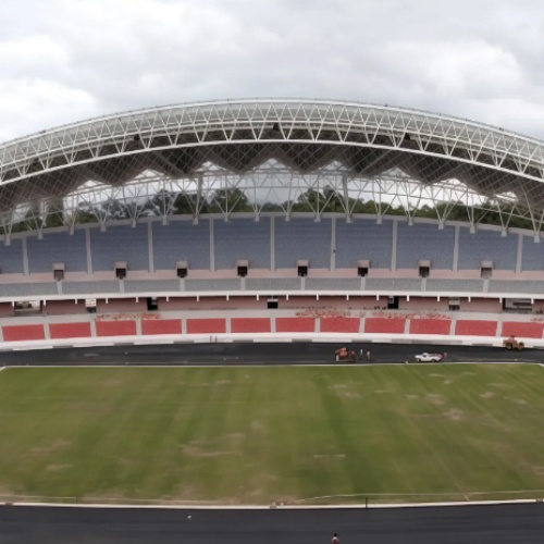
Purpose of this page. Sports-venue steel may include long-span roofs, trusses, space frames, façade supports, seating structures, stairs, catwalks and equipment platforms with visible architectural interfaces. It explains the engineering and procurement route without treating a catalog example as an approved project model.
Application decision context
Long-span movement, erection-stage stability, crowd and roof actions, drainage, façade geometry, lighting and broadcast equipment can interact. Architect, engineer, fabricator and erector need a shared coordinate, tolerance and model-exchange process before shop release.
Required project inputs
- Approved structural model, geometry and erection-stage design
- Wind, snow, seismic, crowd and suspended-equipment loads
- Architectural surfaces, façade, roof and drainage interfaces
- Connection responsibility, tolerance and survey-control plan
- Transport, temporary works, lifting and segment assembly strategy
Configuration and interface route
Trusses, rings, space frames or segmented girders are divided into transportable assemblies with controlled shop and field joints. Node geometry, camber, support movement and façade attachment zones require model-based coordination and survey references.
Manufacturing and verification plan
Material, welding, NDT, trial assembly and dimensional survey requirements are set by the project. Visible steel may add finish criteria beyond structural acceptance. Each member mark and survey record should connect to the approved model revision and erection segment.
Installation, logistics and site coordination
Segment weights, temporary supports, crane positions, weather limits and survey stages need early agreement. Packing follows erection zones and protects finished surfaces. Closure pieces or final connections are released only after the specified survey and engineering review.
Design and supply boundaries
- Named venue references do not prove East Baoyu scope
- Long-span geometry cannot be inferred from photographs
- Architectural finish criteria are separate from structural acceptance
- Erection-stage design responsibility must be identified
Documents to define before release
- Approved geometry model and fabrication drawings
- Erection-stage and temporary-works interface data
- Material, welding and NDT records
- Trial-fit and dimensional survey records
- Finish or coating inspection reports
- Segment packing and erection release schedule
The Product Data Center shows how this application connects to the product family and configuration route. Public catalogs support orientation only. The approved calculation, drawing, bill of material, quotation, ITP and contract define the supplied scope. Use the Evidence Center to request the records applicable to the actual order.
Stable information architecture
Open Product Data Center Product family → configuration → application → evidence
Configuration route
Primary members, Secondary and interface steel, Fabrication and protection route
Application pages
Buildings · Bridges · Power · Oil and gas · Mining · Stadiums and sports centres · Custom structures
Resources and evidence
Steel structures are released from approved drawings, calculations and bills of material rather than a universal website model number. The stable classification is application, structural family, fabrication route and evidence pack.