

Building Steel Structures
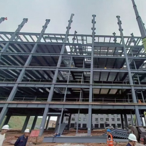
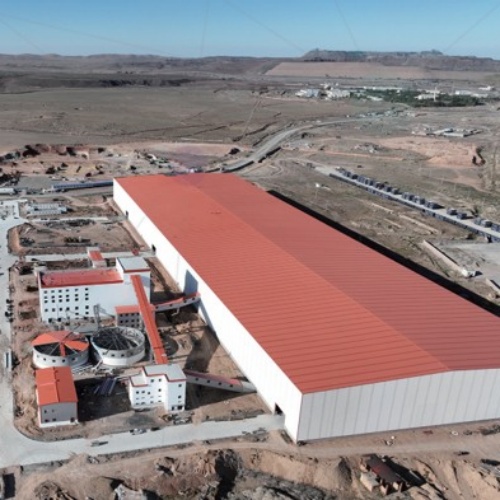
Purpose of this page. Building steelwork can include frames, columns, beams, trusses, bracing, stairs, platforms and secondary support steel released from the project design. It explains the engineering and procurement route without treating a catalog example as an approved project model.
Application decision context
The structural system, grid, spans, stability concept, floor or roof loads, fire strategy, envelope interfaces and erection method must be coordinated before a fabricator can treat the bill of material as stable. Repetition can improve production efficiency, but only after connection families and tolerances are frozen.
Required project inputs
- Design basis, structural model and governing load combinations
- Grid, levels, member schedule and connection design responsibility
- Fire, corrosion, architectural and envelope requirements
- Site crane, access, lifting, temporary stability and erection sequence
- Required fabrication standard, inspection level and document schedule
Configuration and interface route
Primary frames and gravity members are coordinated with bracing, diaphragms and connection zones. Base plates, anchor rods, façade supports, service openings and secondary steel need controlled interfaces. Shop joints and field joints are selected around transport limits, lifting weights, access and the approved erection sequence.
Manufacturing and verification plan
Release connects material grades and thicknesses to drawing revisions and material certificates. The ITP defines dimensional checks, welding controls, NDT where specified, bolt or hole checks, surface preparation, coating or galvanizing records, marking and final release. A standard name alone does not set the project acceptance level.
Installation, logistics and site coordination
Packing should follow erection zones and preserve component marks. Long or heavy pieces require a transport and lifting review. Site changes to bolt holes, plates, welds or member cuts require an approved non-conformance and engineering disposition rather than an undocumented adjustment.
Design and supply boundaries
- No universal bay, span or member size is published
- Fire resistance and coating systems are project-specific
- Foundation and anchor design remain with the stated responsible party
- Fabrication scope does not imply erection or design responsibility
Documents to define before release
- Approved general arrangement and fabrication drawings
- Design responsibility and connection schedule
- Material, welding, NDT and dimensional records
- Coating or galvanizing inspection records
- Packing, marking and erection-zone schedule
- Manufacturing data record and release note
The Product Data Center shows how this application connects to the product family and configuration route. Public catalogs support orientation only. The approved calculation, drawing, bill of material, quotation, ITP and contract define the supplied scope. Use the Evidence Center to request the records applicable to the actual order.
Stable information architecture
Open Product Data Center Product family → configuration → application → evidence
Configuration route
Primary members, Secondary and interface steel, Fabrication and protection route
Application pages
Buildings · Bridges · Power · Oil and gas · Mining · Stadiums and sports centres · Custom structures
Resources and evidence
Steel structures are released from approved drawings, calculations and bills of material rather than a universal website model number. The stable classification is application, structural family, fabrication route and evidence pack.