

Solar Tracking Bracket
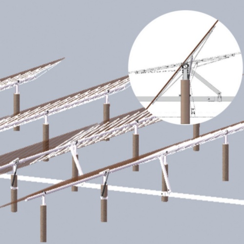
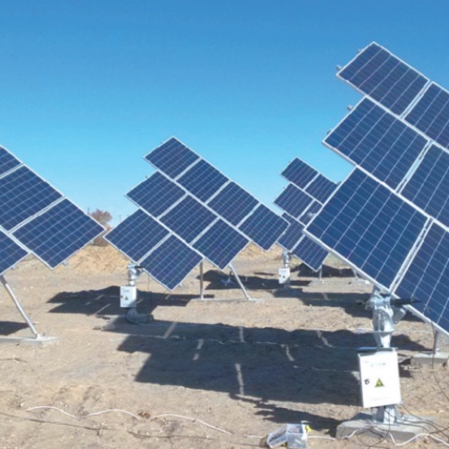
Purpose of this page. A tracker combines structural rows, bearings, drive and transmission, controllers, sensors, communications, stow logic and an operating plan. It explains the engineering and procurement route without treating a catalog example as an approved project model.
Application decision context
The comparison with fixed tilt depends on the weather data, layout, terrain, shading, losses, availability and chosen algorithm. Energy benefit cannot be separated from row length, drive architecture, wind design, auxiliary power, maintenance and recovery assumptions.
Required project inputs
- Module, string, row length, terrain and array layout
- Defined fixed-tilt reference and energy-model assumptions
- Wind, snow, seismic, temperature and drainage criteria
- Power supply, communications, cybersecurity and SCADA interfaces
- Availability target, stow philosophy, maintenance and recovery plan
Configuration and interface route
Single-axis or other architectures are selected through the energy and structural model. Drive location, torque transfer, bearings, controls and row segmentation need coordinated tolerances. Sloped terrain changes backtracking, row geometry, drainage and construction access.
Manufacturing and verification plan
The design basis defines operating and stow cases. FAT may verify controllers, sensors, communications, protection and interfaces where specified. Structural, drive, coating and dimensional records follow the project ITP, while commissioning confirms movement, limits, stow response and monitoring.
Installation, logistics and site coordination
Foundation alignment and row geometry affect binding and tracking accuracy. Packing follows row blocks and separates mechanical, electrical and control components. Commissioning needs a controlled parameter set, fault log, recovery process and handover of software or configuration records.
Design and supply boundaries
- No universal energy-gain percentage is guaranteed
- Stow thresholds are project and control-strategy outputs
- Communications and cybersecurity scope must be defined
- Availability depends on design, operations, spares and response
Documents to define before release
- Energy-model basis and fixed reference
- Structural, drive and control design basis
- Interface and communications schedule
- FAT and commissioning records where required
- Material, coating and inspection records
- O&M, spares and recovery procedures
The Product Data Center shows how this application connects to the product family and configuration route. Public catalogs support orientation only. The approved calculation, drawing, bill of material, quotation, ITP and contract define the supplied scope. Use the Evidence Center to request the records applicable to the actual order.
Technical data framework
Project-specificSolar Tracking System Technical Data Template
A tracker specification must connect the structural design, drive/control architecture, energy model, stow strategy and operations plan. This page does not state a universal energy-gain percentage.
Required design inputs
- Module, string, row length, layout and terrain model
- Defined fixed-tilt reference and energy-model assumptions
- Wind, snow, seismic, temperature and drainage conditions
- Grid power, auxiliary power, communications and cybersecurity route
- Availability target, stow philosophy, maintenance and recovery plan
Decision boundaries
- Energy gain depends on the stated baseline and model
- Stow thresholds and structural limits require project verification
- Backtracking depends on layout, slope and shading assumptions
- Drive, sensor and controller maintenance is part of lifecycle planning
| Parameter | Published value status |
|---|---|
| Tracking axis / architecture | By site and energy model |
| Drive and transmission | By row demand and control philosophy |
| Tracking / backtracking range | By approved algorithm and layout |
| Stow conditions | By structural and operating strategy |
| Control / communications | By project interface specification |
| Power supply | By site electrical design |
| Materials / protection | By exposure and design life |
| Monitoring / fault response | By agreed O&M plan |
Project deliverables
- Energy-model basis and comparison case
- Structural and drive design basis
- Control narrative and interface schedule
- FAT / commissioning records where specified
- Material, coating and inspection records
- Operation, maintenance and recovery procedures
Acceptance rule
- Applicable standard and drawing revision identified
- Inspection characteristic, frequency and acceptance criteria defined
- Records linked to the actual batch, item or installation location
- Exceptions and release authority documented
Catalog dimensions and website examples are selection inputs only. The approved drawing, calculation, quotation, ITP and contract define the supplied product.
Request project data sheetStable information architecture
Open Product Data Center Product family → configuration → application → evidence
Configuration route
Fixed mounting, Tracking mounting, Flexible mounting
Application pages
Fixed PV mounting · Solar tracking systems · Flexible PV mounting
Resources and evidence
The public product families are fixed, tracking and flexible mounting. Geometry, member schedules, controls, foundations, coatings and acceptance records are project outputs.