

Fixed PV Bracket
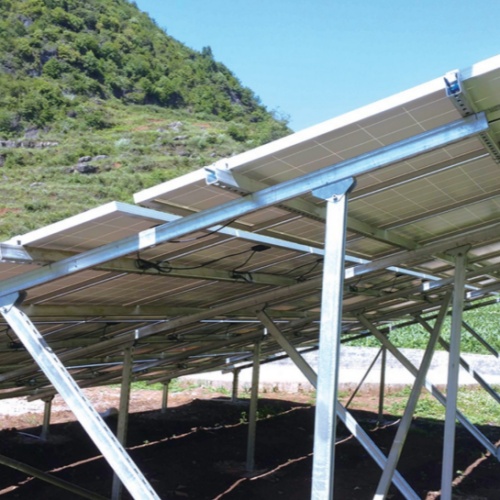
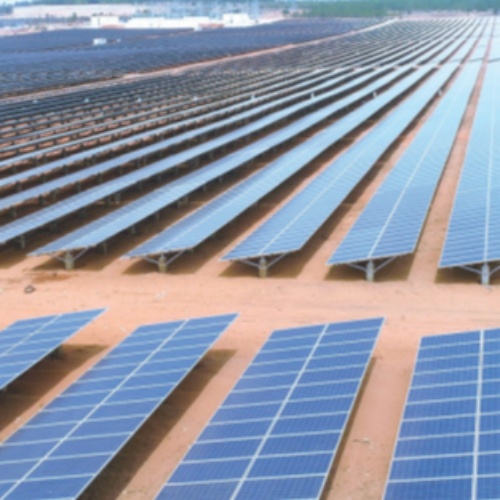
Purpose of this page. Fixed PV mounting holds modules at a project-selected geometry using ground, roof, mountain or carport interfaces and steel or aluminium component routes. It explains the engineering and procurement route without treating a catalog example as an approved project model.
Application decision context
Tilt, table length, portrait or landscape orientation, row spacing, ground clearance and support spacing affect energy, structural demand, land use, drainage and installation. The selected layout must be checked against module clamp zones, wind and snow actions, terrain or roof capacity and maintenance access.
Required project inputs
- Module data, clamp zones, orientation and array layout
- Wind, snow, seismic, temperature and other governing actions
- Topographic survey or roof construction and allowable loads
- Foundation or roof attachment reactions and tolerances
- Exposure, design life, drainage, earthing and maintenance access
Configuration and interface route
Ground systems coordinate posts, foundations, beams, braces and rails with terrain zones. Roof systems coordinate attachment or ballast with waterproofing, structural capacity and drainage. Carport systems add vehicle clearance, impact protection, electrical routes and controlled water discharge.
Manufacturing and verification plan
Structural calculations and approved drawings define member and connection schedules. Manufacturing records connect materials, dimensions, coatings and fasteners to the released bill of material. Site inspection confirms interfaces, alignment, tightening and exceptions against the project ITP.
Installation, logistics and site coordination
Packing by array block or roof zone supports sequencing. Component marks, hardware counts and drawing revisions must remain consistent. Roof loading, access and temporary storage require a method statement; ground projects need survey, foundation and drainage coordination.
Design and supply boundaries
- No universal tilt, span or wind rating is published
- Roof waterproofing and capacity require project review
- Foundation type follows ground and reaction data
- Design life follows material, exposure and maintenance assumptions
Documents to define before release
- Approved layout and structural calculation basis
- Foundation or roof-interface schedule
- Member, connection and fastener drawings
- Material and coating records
- Installation and inspection plan
- O&M access and maintenance information
The Product Data Center shows how this application connects to the product family and configuration route. Public catalogs support orientation only. The approved calculation, drawing, bill of material, quotation, ITP and contract define the supplied scope. Use the Evidence Center to request the records applicable to the actual order.
Technical data framework
Project-specificFixed PV Mounting Technical Data Template
The final fixed-tilt system is defined by the module, layout, structural actions, terrain or roof, corrosion environment and installation method—not by a universal bracket specification.
Required design inputs
- Module dimensions, clamp zones, orientation and array layout
- Wind, snow, seismic and other governing actions
- Terrain survey or roof construction and allowable loads
- Foundation / roof attachment reactions and tolerances
- Exposure, design life, drainage, earthing and maintenance access
Decision boundaries
- Tilt, spans and member sizes are design outputs
- Roof attachment must preserve waterproofing and structural capacity
- Foundation type follows site and reaction data
- Lifecycle cost includes inspection, access and replacement assumptions
| Parameter | Published value status |
|---|---|
| System geometry / tilt | By approved layout |
| Post, beam and rail sections | By structural calculation |
| Material grade | Steel or aluminium route by specification |
| Connections / fasteners | By calculation and interface drawing |
| Foundation / roof interface | By project design |
| Corrosion protection | By exposure and design life |
| Installation tolerances | By approved drawings |
| Inspection scope | By project ITP |
Project deliverables
- Layout, reactions and approved drawings
- Structural calculation basis
- Bill of materials and packing schedule
- Material and coating records
- Dimensional / final inspection report
- Installation and maintenance information
Acceptance rule
- Applicable standard and drawing revision identified
- Inspection characteristic, frequency and acceptance criteria defined
- Records linked to the actual batch, item or installation location
- Exceptions and release authority documented
Catalog dimensions and website examples are selection inputs only. The approved drawing, calculation, quotation, ITP and contract define the supplied product.
Request project data sheetStable information architecture
Open Product Data Center Product family → configuration → application → evidence
Configuration route
Fixed mounting, Tracking mounting, Flexible mounting
Application pages
Fixed PV mounting · Solar tracking systems · Flexible PV mounting
Resources and evidence
The public product families are fixed, tracking and flexible mounting. Geometry, member schedules, controls, foundations, coatings and acceptance records are project outputs.